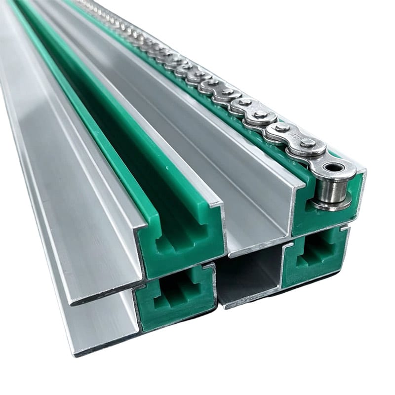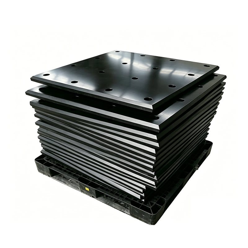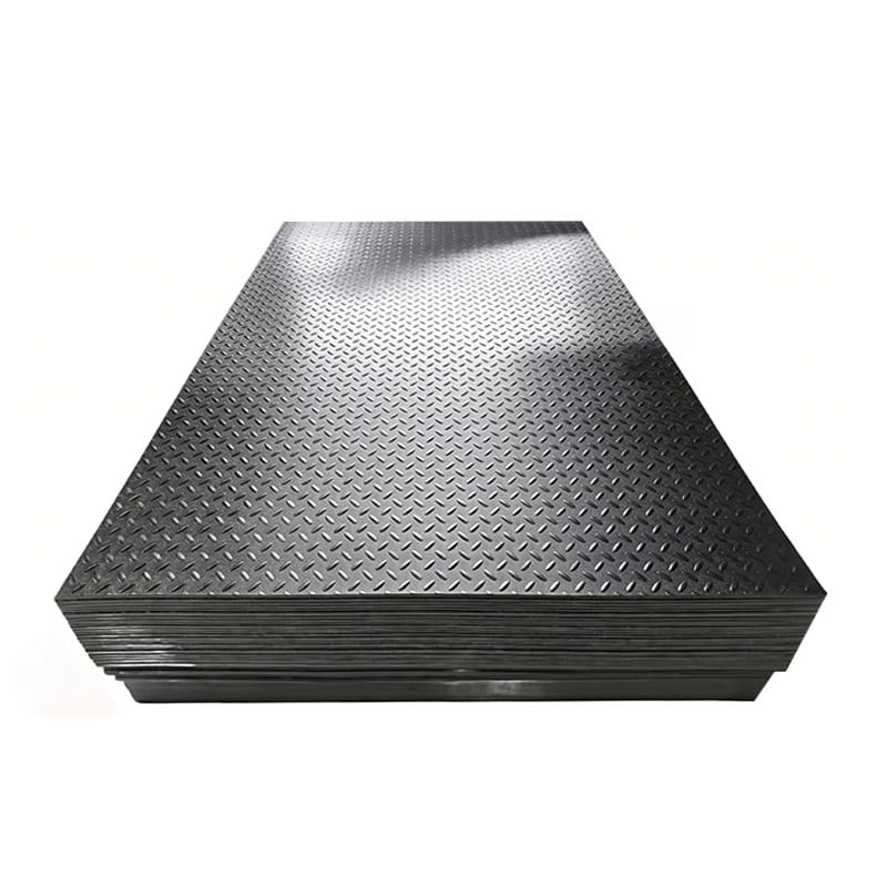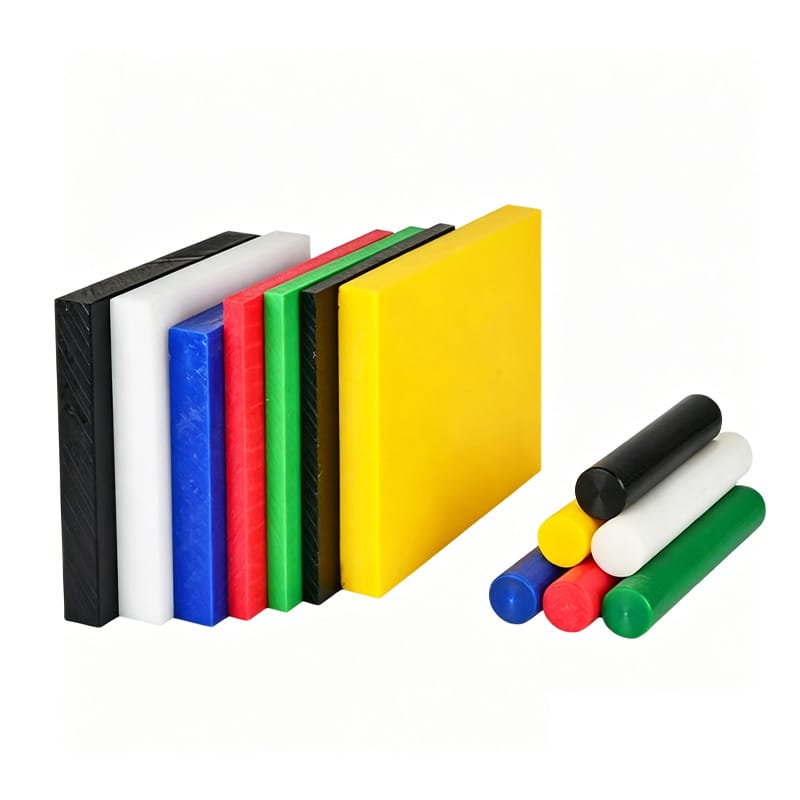
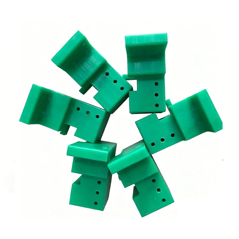
Ordering a custom UHMWPE part often begins with a simple email attachment: a STEP file, a 2D drawing, or sometimes a worn physical sample.
What happens after that determines whether the final component fits, functions, and can be reproduced consistently in future batches.
Unlike buying standard plastic sheet, custom UHMWPE CNC machining involves much more than cutting a shape from stock. The manufacturer has to understand the function of the part, choose suitable raw material, review tolerances, establish datums, plan the machining sequence, inspect critical dimensions, and package the finished parts so they arrive without deformation or identification problems.
For OEM buyers, conveyor manufacturers, equipment builders, and maintenance teams, understanding this workflow makes supplier evaluation much easier.
A capable machining supplier should be able to explain how a drawing becomes a controlled production process rather than simply saying, “Send us the file and we will make it.”
This guide walks through the typical process from CAD review to finished custom UHMWPE machined parts, including the information buyers should prepare before requesting a quotation.
Why UHMWPE Machining Needs a Different Approach from Metal Machining
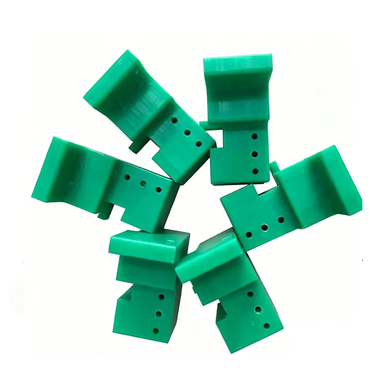
UHMWPE is an engineering plastic with very different physical behavior from steel or aluminum.
That affects both design and machining.
Compared with many metals, UHMWPE is:
- Much softer
- More flexible
- More sensitive to clamping pressure
- More affected by thermal expansion
- Capable of deforming under sustained load
- Less suitable for unnecessarily tight tolerances
This does not mean UHMWPE cannot be machined accurately.
It means the part should be designed and inspected according to how the material actually behaves.
A drawing copied directly from a steel part may contain tolerances or wall sections that are inappropriate for UHMWPE.
Good suppliers usually review the file before quoting rather than automatically accepting every dimension as equally critical.
Step One: Reviewing the STEP File and 2D Drawing
The first stage of a custom UHMWPE CNC machining project should be technical review.
The 3D model shows the part geometry, while the 2D drawing usually carries the manufacturing requirements.
A supplier should review both when available.
What Is Checked During File Review?
Typical checks include:
- Overall dimensions
- Critical tolerances
- Hole diameters
- Hole positions
- Slots
- Counterbores
- Countersinks
- Pockets
- Wall thickness
- Radii
- Surface requirements
- Datum structure
- Material specification
The manufacturer also checks whether the requested geometry can be held securely during machining.
Some parts look simple in CAD but are difficult to fixture because they are:
- Thin
- Long
- Flexible
- Irregularly shaped
Fixturing needs to be considered before machining begins.
Why a STEP File Alone May Not Be Enough
A STEP file contains geometry, but it usually does not communicate all engineering requirements.
It may not define:
- Which dimensions are critical
- General tolerances
- Surface finish
- Inspection points
- Material grade
- Quantity
- Revision number
For repeat OEM production, a controlled 2D drawing is therefore highly valuable.
Ideally, the RFQ includes both:
3D model + 2D drawing
The model helps programming and visualization.
The drawing defines what the finished part must meet.
Step Two: Confirming the UHMWPE Material Grade
Before cutting material, the supplier needs to confirm what UHMWPE grade is required.
Not all polyethylene described as “UHMWPE” is necessarily identical.
Differences can include:
- Resin source
- Molecular-weight range
- Additives
- Color
- Reprocessed content
- Antistatic modification
- UV stabilization
The exact requirements depend on the application.
Standard UHMWPE Applications
Standard UHMWPE may be suitable for parts such as:
- Wear plates
- Conveyor guides
- Sliding blocks
- Scrapers
- Support components
- Bushings
- Machine wear parts
Modified UHMWPE Applications
Some applications may require additional properties such as:
- Antistatic behavior
- UV resistance
- Specific color
- Regulatory documentation
- Custom material formulation
These requirements should be stated before production.
Material cannot be reliably selected from the final part dimensions alone.
Step Three: Preparing Raw Material
Custom UHMWPE parts are often machined from:
- Sheet
- Plate
- Rod
- Block
- Extruded profile
The raw material must be large enough to allow machining allowance around the final geometry.
For example, if a finished part requires accurately machined parallel surfaces, the raw stock may need extra material so both faces can be processed.
Why Raw Material Flatness Matters
Plastic sheet can have different flatness characteristics from precision metal plate.
For large parts, the manufacturer should consider:
- Raw sheet flatness
- Residual stress
- Storage method
- Cutting allowance
- Final thickness tolerance
These factors become more important as part size increases.
Step Four: Cutting the Blank
The first physical manufacturing operation is often blank preparation.
A larger UHMWPE sheet may be cut into smaller pieces before CNC machining.
Blank cutting helps:
- Reduce machine time
- Simplify handling
- Improve fixturing
- Organize batch production
The blank should still include enough excess material for final machining where necessary.
For simple parts, some exterior dimensions may be cut close to final size.
For precision components, critical faces are usually finished on the CNC machine.
Step Five: Planning the Machining Sequence
Machining sequence matters because UHMWPE can move or deform when material is removed.
A good machining plan may include:
- Rough machining
- Releasing the part
- Repositioning
- Finish machining
- Drilling
- Profiling
- Deburring
The exact sequence depends on geometry.
Why Machining Sequence Matters
Consider a long thin guide rail.
If too much material is removed from one side at once, the part may change shape.
A more balanced approach may be required.
Similarly, a complex component with several deep pockets may need staged machining so the remaining walls are not distorted during clamping.
This is one reason custom UHMWPE CNC machining should be handled by suppliers familiar with engineering plastics rather than treated exactly like metal machining.
Step Six: Choosing the Right Cutting Tools
UHMWPE generally machines well with sharp cutting tools.
The objective is to produce a clean cut rather than rubbing or excessively heating the plastic.
Machining parameters depend on:
- Tool geometry
- Machine rigidity
- Part geometry
- Material grade
- Depth of cut
- Required surface quality
Sharp tools help reduce:
- Burrs
- Heat buildup
- Rough edges
- Material smearing
Tool selection is particularly important around small slots, thin walls, and drilled features.
Step Seven: Controlling Heat During CNC Machining
Heat is an important issue when machining thermoplastics.
Too much heat can affect:
- Dimensional accuracy
- Surface finish
- Burr formation
- Local material behavior
Heat can come from:
- Excessive spindle speed
- Dull tools
- Poor chip removal
- Continuous tool contact
The machining process should therefore balance cutting speed and feed so the tool cuts cleanly.
Effective chip removal is also important.
UHMWPE chips can accumulate around the tool and part if they are not cleared properly.
Step Eight: Fixturing Without Distorting the Part
One of the most important skills in machining plastic is controlling clamping force.
Metal parts can often tolerate high clamping pressure.
UHMWPE may deform under excessive force.
If the part is inspected while still heavily clamped, dimensions may appear correct.
After unclamping, the part may relax and change.
Common UHMWPE Fixturing Methods
Depending on geometry, manufacturers may use:
- Mechanical clamps
- Soft jaws
- Vacuum fixtures
- Custom support blocks
- Sacrificial plates
The fixture should support the part sufficiently without squeezing it out of shape.
Long or thin parts may need support across a larger area.
Step Nine: Machining Holes, Slots and Pockets

Many custom UHMWPE parts are not simply rectangular blocks.
Typical features include:
- Through holes
- Thread clearance holes
- Counterbores
- Countersinks
- Mounting slots
- Guide grooves
- Recesses
- Pockets
These features should be evaluated individually.
Holes Near an Edge
Hole edge distance matters.
A hole placed too close to an edge may create a weak section, especially when the part carries load.
Deep Pockets
Deep pockets reduce wall thickness and may make the part more flexible.
The designer should confirm whether the remaining section is sufficient for the application.
Mounting Slots
Slots may be used to allow:
- Adjustment
- Thermal expansion
- Assembly tolerance
Their orientation should reflect the intended movement of the part.
Step Ten: Managing Tolerances
Tolerance is one of the most important topics in custom UHMWPE machining.
A common mistake is applying metal-style tolerances to every dimension.
This can increase cost without improving function.
Identify Critical Dimensions
Critical dimensions may include:
- Bearing locations
- Chain contact profile
- Assembly width
- Hole center distance
- Slot position
- Mating surfaces
These deserve more attention than non-functional outside dimensions.
Use General Tolerances Where Appropriate
Features that do not affect fit or function may not need highly restrictive tolerance.
A drawing that distinguishes critical from non-critical features is easier to manufacture consistently.
Why Temperature Matters During Inspection
Plastic dimensions can change with temperature.
Large UHMWPE parts can show measurable dimensional differences if:
- Machined warm
- Inspected immediately
- Stored in a different temperature environment
For precision projects, buyer and supplier should agree on the inspection conditions.
This is particularly important when tolerances are tight relative to the overall part size.
Step Eleven: First Article Inspection
Before producing a large batch, it is often useful to inspect one or several first parts.
This process is commonly called first article inspection.
The purpose is to confirm that:
- The program is correct
- The fixture is suitable
- Critical dimensions meet requirements
- The material is correct
- Part identification is correct
For OEM projects, approving the first article can prevent an error from being repeated across an entire batch.
What Should Be Included in a First Article Check?
Depending on the project, the inspection may include:
- Overall dimensions
- Critical hole locations
- Thickness
- Profile dimensions
- Slot dimensions
- Visual appearance
- Material confirmation
For repeat orders, the approved first article can also act as a reference for future production.
Step Twelve: Batch CNC Production
Once the first part is approved, the process can move into batch production.
Consistency becomes the main focus.
The supplier should control:
- Material batch
- CNC program
- Fixturing
- Tool condition
- Inspection frequency
- Part identification
For larger quantities, process stability is more important than checking only the first and last part.
Why Tool Wear Still Matters in Plastic Machining
UHMWPE does not wear tools in the same way as abrasive metals, but tool condition still affects finished quality.
A dull cutter can lead to:
- Rougher edges
- Burrs
- Increased heat
- Different dimensions
Tool condition should therefore be monitored during batch production.
Step Thirteen: Deburring and Edge Finishing
After machining, parts usually need some finishing.
Possible operations include:
- Removing burrs
- Cleaning sharp machining edges
- Removing loose chips
- Inspecting corners
The goal is not necessarily to polish every surface.
Functional plastic components generally need clean, consistent edges rather than decorative finishing.
If a specific edge radius or chamfer is required, it should be shown on the drawing.
Step Fourteen: Final Dimensional Inspection
Finished parts should be checked against the drawing.
Inspection methods may include:
- Calipers
- Micrometers
- Height gauges
- Pin gauges
- Custom gauges
- Coordinate measurement methods where appropriate
The inspection method should match the dimension.
For example, a simple outside dimension does not require the same inspection method as a complex chain-guide profile.
Inspection Should Focus on Functional Features
For efficient quality control, identify features that directly affect:
- Assembly
- Alignment
- Movement
- Wear
- Interchangeability
These should receive the highest inspection priority.
Paowo Group can support inspection requirements for custom UHMWPE machined parts based on project drawings and agreed specifications.
Step Fifteen: Cleaning and Part Identification
Before packaging, machining chips and debris should be removed.
For OEM projects, each component may also need identification.
Options can include:
- Part number
- Batch number
- Drawing revision
- Customer code
- Installation position
Identification becomes especially useful when multiple similar parts are packed together.
Why Drawing Revision Control Matters
A serious OEM problem can occur when an old drawing is accidentally used for a new order.
The supplier and buyer should therefore control:
- Drawing number
- Revision number
- STEP file revision
- Approved changes
If a dimension changes after first article approval, the updated revision should replace the old version in production records.
This is essential for long-term repeat orders.
Step Sixteen: Packaging Custom UHMWPE Parts
Packaging is often overlooked during supplier evaluation.
A perfectly machined part can still arrive damaged or distorted if packed poorly.
Packaging should consider:
- Part weight
- Part length
- Thin sections
- Finished surfaces
- Quantity per box
- Transport method
Long UHMWPE Parts
Long guides and strips should be supported so they do not remain heavily bent during transport.
Small CNC Components
Small parts should be separated or grouped in a way that prevents:
- Mixing
- Missing quantities
- Surface damage
Part Labels
Packaging labels can include:
- Part number
- Quantity
- Batch
- Purchase order
- Drawing revision
This makes warehouse and assembly handling easier.
From Sample to CAD: What If No Drawing Exists?
Not every replacement project starts with a STEP file.
Sometimes the buyer only has a worn part.
A manufacturer may be able to reverse engineer the component, but caution is necessary.
Do Not Copy Wear Damage
A used sample may have:
- Worn surfaces
- Enlarged holes
- Distorted edges
- Reduced thickness
Those dimensions should not automatically become the dimensions of the new part.
Where possible, reverse engineering should also use:
- Mating part dimensions
- Machine drawings
- Chain dimensions
- Mounting positions
- Unworn surfaces
The goal is to reproduce the original function, not reproduce the worn condition.
What Information Should Buyers Send for a Custom UHMWPE Quote?
A complete RFQ helps the manufacturer quote more accurately and reduces back-and-forth communication.
Files
Provide:
- STEP file
- 2D PDF drawing
- DXF where useful
- Photos if replacing an existing component
Material Information
Provide:
- Required UHMWPE grade
- Color
- Any additive requirements
- Documentation requirements
Quantity
State:
- Prototype quantity
- First production quantity
- Expected annual volume
Quantity can affect machining strategy and fixture design.
Tolerance Requirements
Clearly identify:
- Critical dimensions
- General tolerances
- Special inspection requirements
Application Information
Explain what the part does.
For example:
- Chain guide
- Wear plate
- Sliding block
- Scraper
- Conveyor component
Knowing the function can help the supplier identify potential manufacturing concerns.
Common Custom UHMWPE Machining Mistakes
Several issues repeatedly cause delays or unnecessary cost.
Sending Only a Screenshot
A screenshot is useful for discussion but usually not sufficient for manufacturing.
Send actual CAD and drawing files.
Applying Tight Tolerances Everywhere
This increases machining and inspection effort without necessarily improving performance.
Not Identifying the Material Grade
“White plastic” or “PE” is not a complete engineering material specification.
Copying Metal Part Geometry Directly
A plastic replacement may require different thickness, mounting or clearance.
Ignoring Thermal Expansion
Long UHMWPE guides should be designed with dimensional movement in mind.
Ordering a Large Batch Before Approving the First Part
For new OEM parts, first article approval can reduce risk.
Failing to Control Revisions
Old drawings can create expensive production errors.
Custom UHMWPE CNC Machining FAQ
Can UHMWPE Be CNC Machined?
Yes. UHMWPE can be CNC milled, routed, drilled, turned and profiled into many custom engineering components.
What File Format Is Best for Custom UHMWPE Parts?
A STEP file combined with a dimensioned 2D drawing is usually highly useful. The STEP file provides geometry, while the drawing defines tolerances and other manufacturing requirements.
Can You Machine UHMWPE from a Physical Sample?
Yes, a sample can be used as a reference, but worn surfaces should not automatically be copied. Original functional dimensions should be reconstructed where possible.
Can UHMWPE Hold Tight Tolerances?
UHMWPE can be machined accurately, but tolerances should reflect the material’s thermal expansion, flexibility and application requirements.
Can UHMWPE Parts Have Countersunk Holes?
Yes. Countersinks, counterbores, slots and other mounting features can be CNC machined when properly designed.
Should I Order a Prototype First?
For new or complex parts, a prototype or first article can be useful before committing to larger production quantities.
Can Part Numbers Be Added?
Yes. Depending on the project, part numbers, batch identification or customer markings can be added to simplify assembly and traceability.
Can Paowo Produce Repeat OEM Orders?
Repeat production is possible when material specifications, drawings, revisions and inspection requirements are clearly controlled.
Custom UHMWPE CNC Machining RFQ Checklist
Before requesting a quote, prepare the following.
Design Files
- STEP file
- 2D drawing
- DXF if required
- Reference photographs
Material
- UHMWPE grade
- Color
- Special additives
- Required material documents
Quantity
State:
- Prototype quantity
- First production quantity
- Expected annual volume
Quantity can affect machining strategy and fixture design.
Tolerance Requirements
Clearly identify:
- Critical dimensions
- General tolerances
- Special inspection requirements
Application Information
Explain what the part does.
For example:
- Chain guide
- Wear plate
- Sliding block
- Scraper
- Conveyor component
Knowing the function can help the supplier identify potential manufacturing concerns.
Common Custom UHMWPE Machining Mistakes
Several issues repeatedly cause delays or unnecessary cost.
Sending Only a Screenshot
A screenshot is useful for discussion but usually not sufficient for manufacturing.
Send actual CAD and drawing files.
Applying Tight Tolerances Everywhere
This increases machining and inspection effort without necessarily improving performance.
Not Identifying the Material Grade
“White plastic” or “PE” is not a complete engineering material specification.
Copying Metal Part Geometry Directly
A plastic replacement may require different thickness, mounting or clearance.
Ignoring Thermal Expansion
Long UHMWPE guides should be designed with dimensional movement in mind.
Ordering a Prototype Before Approving the First Part
For new OEM parts, first article approval can reduce risk.
Failing to Control Revisions
Old drawings can create expensive production errors.
Custom UHMWPE CNC Machining FAQ
Can UHMWPE Be CNC Machined?
Yes. UHMWPE can be CNC milled, routed, drilled, turned and profiled into many custom engineering components.
What File Format Is Best for Custom UHMWPE Parts?
A STEP file combined with a dimensioned 2D drawing is usually highly useful. The STEP file provides geometry, while the drawing defines tolerances and other manufacturing requirements.
Can You Machine UHMWPE from a Physical Sample?
Yes, a sample can be used as a reference, but worn surfaces should not automatically be copied. Original functional dimensions should be reconstructed where possible.
Can UHMWPE Hold Tight Tolerances?
UHMWPE can be machined accurately, but tolerances should reflect the material’s thermal expansion, flexibility and application requirements.
Can UHMWPE Parts Have Countersunk Holes?
Yes. Countersinks, counterbores, slots and other mounting features can be CNC machined when properly designed.
Should I Order a Prototype First?
For new or complex parts, a prototype or first article can be useful before committing to larger production quantities.
Can Part Numbers Be Added?
Yes. Depending on the project, part numbers, batch identification or customer markings can be added to simplify assembly and traceability.
Can Paowo Produce Repeat OEM Orders?
Repeat production is possible when material specifications, drawings, revisions and inspection requirements are clearly controlled.
Custom UHMWPE CNC Machining RFQ Checklist
Before requesting a quote, prepare the following.
Design Files
- STEP file
- 2D drawing
- DXF if required
- Reference photographs
Material
- UHMWPE grade
- Color
- Special additives
- Required material documents
Dimensions
- Overall size
- Critical tolerances
- Hole locations
- Slots
- Pockets
- Profiles
Quantity
- Prototype quantity
- Production quantity
- Expected annual demand
Quality Requirements
- First article inspection
- Critical inspection points
- Dimensional report
- Batch traceability
Packaging
- Part labels
- Quantity per carton
- Pallet requirements
- Special protection for long parts
Providing these details allows the supplier to evaluate not only the part price, but also the complete manufacturing route.
Conclusion
A reliable custom UHMWPE CNC machining process begins long before the cutter touches the plastic.
It starts with understanding the drawing, the function of the part, the material grade and which dimensions actually matter.
From there, the manufacturer has to control:
- Raw material
- Blank preparation
- Machining sequence
- Tool condition
- Fixturing
- Heat
- Tolerances
- First article inspection
- Batch production
- Revision control
- Packaging
For buyers, this workflow is also a useful way to evaluate suppliers.
Instead of asking only, “Do you have CNC machines?”, ask how the supplier reviews drawings, manages first articles, controls critical dimensions and handles repeat production.
Paowo Group provides custom UHMWPE machined parts and OEM/ODM customization for industrial plastic components.
Send your STEP file, 2D drawing, material requirement, quantity, critical tolerances and application information for a manufacturability review and quotation.