Selecting a UHMWPE conveyor guide by overall width alone is one of the easiest ways to order a part that looks correct on paper but performs poorly in the machine.
The chain may technically fit inside the guide, yet still run too tightly against the side walls. Another profile may provide too much clearance, allowing the chain to move laterally and strike the guide repeatedly. In curved sections, an apparently small mismatch can become even more noticeable because side loading increases as the chain changes direction.
That is why chain guide profile selection should begin with the chain itself.
The useful inputs are not simply “20 mm chain” or “standard roller chain.” Buyers and designers should consider the complete cross-section, including chain width, side plates, rollers, pin projection, running direction and the surfaces that are actually intended to contact the UHMWPE guide.
For new conveyor systems, a controlled chain drawing and guide cross-section provide the strongest starting point.
For replacement projects, a worn guide can be useful, but it should not be copied blindly. Wear may have enlarged the groove, reduced side-wall thickness or changed the original running clearance.
Paowo Group manufactures UHMWPE chain guides and custom conveyor profiles based on chain dimensions, drawings, samples and operating conditions.
Why Chain Guide Profile Selection Starts with the Chain

A chain guide has one primary job: control the chain’s intended path while allowing it to move with acceptable friction and clearance.
That sounds simple, but chains vary significantly.
Differences may include:
- Overall width
- Inner width
- Side-plate thickness
- Roller diameter
- Roller width
- Pin length
- Attachment geometry
- Guide-contact surface
A reliable chain guide profile selection process therefore starts by identifying the exact chain model.
Useful information includes:
- Chain manufacturer
- Chain series
- Chain number
- Manufacturer drawing
- Nominal pitch
- Overall chain width
- Side-plate dimensions
If this information is available, it is more reliable than measuring a heavily worn chain already in service.
Which Chain Dimension Actually Controls the Guide Width?
There is no single answer for every chain-guide design.
The controlling dimension depends on how the guide is intended to contact and support the chain.
Some profiles guide the chain mainly by:
- Outer side plates
Others may support:
- Rollers
- Link plates
- Bottom surfaces
- Multiple contact surfaces
That means chain guide profile selection should identify the functional contact area before defining the groove.
A supplier should not simply take the maximum overall chain width and add an arbitrary amount of clearance.
The complete chain profile should be reviewed.
Why Overall Chain Width Is Not Always Enough
Suppose two chains have the same nominal overall width.
One may have:
- Thick side plates
- Narrow roller section
while another has:
- Thinner side plates
- Wider roller geometry
A generic U-shaped guide may interact differently with each chain.
The same issue appears with chains that include:
- Extended pins
- Attachments
- Special plates
If those features pass close to the guide walls, the chain guide profile selection must account for them.
How Side Plates Affect Chain Guide Profile Selection
Side plates are particularly important because they frequently define lateral chain geometry.
A guide that controls the chain by its side plates needs sufficient clearance to prevent unnecessary rubbing while still limiting excessive side movement.
Important side-plate inputs include:
- Plate thickness
- Plate height
- Maximum overall plate width
- Projection beyond roller or bushing
For custom profiles, it is useful to mark on the chain drawing exactly which surface is expected to run against the UHMWPE.
That reduces ambiguity during chain guide profile selection.
What Happens If the Guide Is Too Narrow?
A guide groove with insufficient width can increase continuous side contact.
Possible symptoms include:
- High friction
- Heat buildup
- Increased drive load
- Rapid guide polishing
- Uneven side-wall wear
- Chain binding
These problems may become more noticeable after the conveyor warms up.
UHMWPE and surrounding metal components can experience different thermal movement, so a guide that feels acceptable during cold assembly may become tighter in service.
This is why chain guide profile selection should consider operating temperature as well as nominal dimensions.
What Happens If the Guide Is Too Wide?
Too much clearance creates a different problem.
The chain may:
- Wander laterally
- Strike the guide walls
- Produce noise
- Track inconsistently
- Create impact-style wear
On product conveyors, excessive chain movement can also influence:
- Transfer alignment
- Product stability
- Sprocket engagement
The goal of chain guide profile selection is therefore not maximum clearance.
It is controlled functional clearance.
Running Clearance Should Be Functional, Not Arbitrary
There is no responsible universal rule such as:
“Always add 1 mm.”
The appropriate clearance depends on:
- Chain manufacturing tolerance
- Chain wear
- Guide length
- Speed
- Temperature
- Alignment
- Curves
- Contamination
For critical applications, the buyer and supplier should review the actual chain specification rather than apply a generic allowance.
This also helps prevent a common error: using a worn chain to establish the original guide profile.
How Chain Wear Changes the Apparent Required Profile
Chains change during service.
Wear may affect:
- Pins
- Bushings
- Rollers
- Side plates
- Effective pitch
A worn chain can move differently inside the guide from a new one.
If the replacement guide is designed only around the old worn chain, chain guide profile selection may build excessive clearance into the new component.
For retrofit work, measure both:
- Existing chain
- New chain specification
where possible.
Why Running Direction Matters
The guide profile should be reviewed in the context of the direction the chain travels.
Running direction can influence:
- Entry geometry
- Transition edges
- Joint orientation
- Wear location
A profile may need a smooth entry where the chain first engages the guide.
Sharp transitions can create repeated impact.
For long systems, mark chain direction on the drawing used for chain guide profile selection.
This is especially helpful where several guide sections are not symmetrical.
Roller Chains Need Different Contact Logic from Flat-Top Chains
Not all conveyor chains should be treated the same.
Traditional roller chains may use guides that support or contain specific chain features.
Flat-top or tabletop chains may involve a different geometry and different support surfaces.
Other conveyor chain types can include:
- Attachment chains
- Side-flexing chains
- Plastic chains
- Steel chains
The guide should match the actual chain family.
A profile used successfully with one chain type should not automatically be copied into another conveyor.
Bottom Support vs Side Guidance
Some chain guides mainly provide bottom support.
Others mainly control lateral movement.
Many do both.
This distinction should be clear during chain guide profile selection.
Bottom-Support Guides
Important dimensions can include:
- Support width
- Base thickness
- Contact surface
Side-Guiding Profiles
Important dimensions can include:
- Groove width
- Side-wall height
- Lateral clearance
Combined Profiles
The guide may need to control both vertical and lateral position.
The cross-section should clearly show which surfaces are functional.
How Groove Depth Affects Chain Control
Groove width is only one dimension.
Groove depth determines how deeply the chain sits inside the guide.
If the groove is too shallow, the chain may not receive enough lateral guidance.
If it is too deep, the guide may contact areas that were not intended to rub.
Deep profiles can also affect:
- Cleaning
- Debris accumulation
- Access
The correct groove depth depends on the chain geometry and machine design.
Why Side-Wall Height Matters
Higher side walls can provide stronger lateral containment.
But unnecessarily high walls may also:
- Increase material use
- Trap debris
- Interfere with attachments
- Create additional rubbing surfaces
For chain guide profile selection, the wall should be high enough to perform its guiding function without creating unnecessary interference.
A section drawing makes this much easier to evaluate.
Chain Attachments Must Be Included in the Cross-Section Review
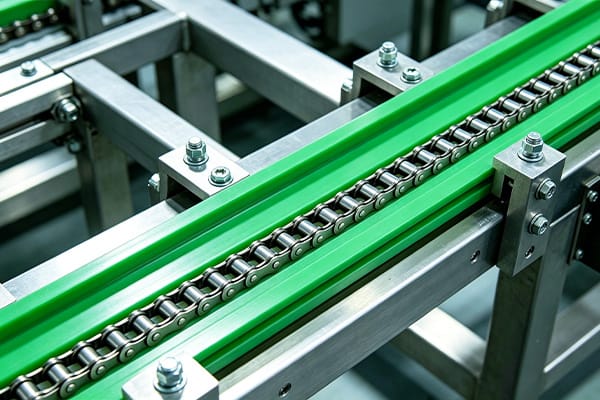
Some conveyor chains include attachments such as:
- Extended pins
- Tabs
- Flights
- Product carriers
These features may pass very close to the guide.
If the profile is designed from a standard base-chain drawing only, an attachment may collide with the guide during operation.
Therefore, a complete chain guide profile selection package should include the actual chain configuration used in the machine.
Why Curve Sections Need More Clearance Review
A chain traveling through a curve experiences lateral force against the guide.
This means a profile that runs quietly on a straight conveyor may behave differently in a curved section.
Important curve inputs include:
- Centerline radius
- Arc angle
- Chain type
- Speed
- Load
The side of the guide carrying the curve load may wear faster.
When performing chain guide profile selection for curved conveyors, the supplier should know which wall receives the primary chain pressure.
Tight Curves Increase Side Loading
As curve radius decreases, chain side loading can increase.
This may result in:
- Higher friction
- Heat
- Faster side-wall wear
If an existing conveyor has one curved guide wearing repeatedly, increasing material thickness alone may not fix the root cause.
The system should also be checked for:
- Radius
- Chain suitability
- Alignment
- Speed
Straight-to-Curve Transitions Should Be Smooth
Where straight and curved guide sections meet, the chain should transition without encountering a step.
Poor transitions can create:
- Impact
- Noise
- Localized wear
During chain guide profile selection, make sure adjacent sections share a compatible:
- Groove centerline
- Groove depth
- Profile height
This is especially important when guides come from different drawings or suppliers.
How Conveyor Speed Changes Profile Requirements
Speed influences sliding distance and frictional heating.
A high-speed chain can expose a profile to much more cumulative contact in the same operating period.
Therefore, chain guide profile selection should include:
- Normal speed
- Maximum speed
- Operating hours per day
High-speed systems may be more sensitive to:
- Tight clearance
- Alignment
- Surface condition
If overheating is already occurring, the profile should not be redesigned without also reviewing chain tension and conveyor alignment.
Load Can Change Chain-to-Guide Contact
A heavily loaded chain may sit or track differently from a lightly loaded chain.
Product load can increase:
- Chain tension
- Contact pressure
- Wear
Accumulation conveyors can create additional loading in specific zones.
When selecting a guide profile, describe whether the chain is:
- Carrying load
- Running empty
- In accumulation
- On the return side
The same chain may need different guide considerations in different sections of the machine.
Temperature Can Reduce Designed Clearance
Long UHMWPE guides can expand with temperature.
The chain and supporting steel structure also change dimensions, but not necessarily at the same rate.
If the groove is already tight at installation, temperature changes may reduce functional clearance.
Therefore, chain guide profile selection should include:
- Minimum operating temperature
- Normal operating temperature
- Maximum operating temperature
For long guides, mounting design should also allow appropriate thermal movement.
Contamination Requires Extra Running Clearance Consideration
Dust, fibers, product debris or metal particles can enter the chain-guide interface.
A profile designed with extremely tight clearance may become vulnerable to debris.
Possible consequences include:
- Scoring
- Jamming
- Heat
- Accelerated abrasion
This does not mean the guide should simply be made very loose.
Instead, chain guide profile selection should reflect the actual cleanliness of the environment.
For dirty industrial conveyors, contamination management can be as important as the nominal profile.
Lubrication Conditions Should Be Included
Some chains run dry.
Others use:
- Oil
- Grease
- Water-based lubrication
- Intermittent lubrication
Lubrication changes friction and debris behavior.
A guide used successfully on a lubricated chain may perform differently in a dry-running system.
Always include lubrication condition when requesting a custom UHMWPE profile.
Why Guide Base Thickness Matters
The guide must have enough material beneath the chain-contact surface for:
- Wear allowance
- Mounting
- Stiffness
A very shallow base may flex or wear through quickly.
An excessively thick base may:
- Waste material
- Interfere with conveyor geometry
- Increase cost
The ideal base thickness depends on:
- Support spacing
- Chain load
- Profile size
- Wear allowance
The chain guide profile selection process should therefore include both internal groove geometry and external guide dimensions.
Support Spacing Affects Profile Stiffness
A guide supported continuously by a metal carrier behaves differently from one spanning between mounting brackets.
Long unsupported spans can allow:
- Deflection
- Vibration
- Uneven chain contact
If the guide is mounted at discrete points, provide support spacing.
A profile that is adequate with continuous support may be too flexible when brackets are far apart.
Metal Carrier Profiles Can Simplify Replacement
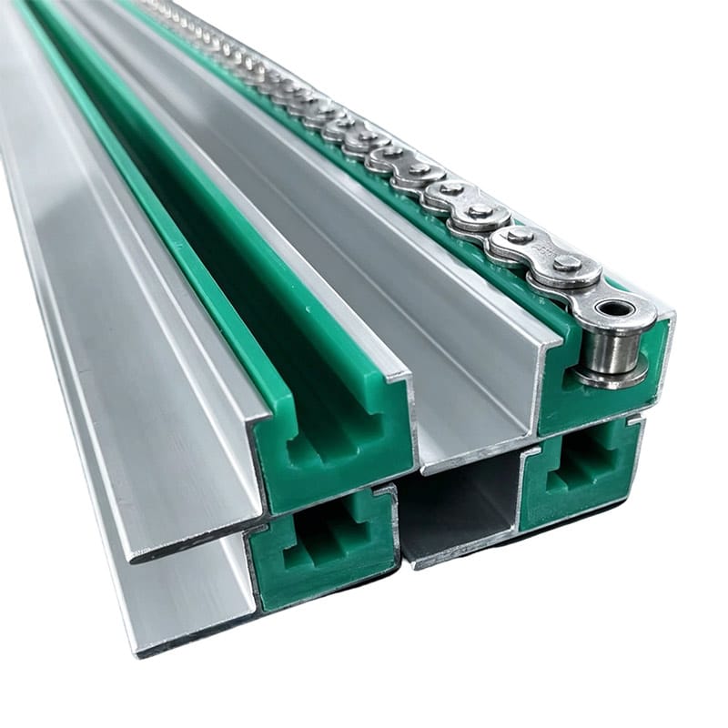
Some UHMWPE guides are designed to fit into a metal carrier.
This can provide:
- Defined alignment
- Easy replacement
- Support along the guide length
The plastic profile must match the carrier dimensions accurately enough to remain secure without creating unnecessary installation difficulty.
In this type of chain guide profile selection, both chain geometry and carrier geometry are required.
Snap-In Profiles Need Controlled Retention Geometry
Snap-in guide profiles can reduce fastening requirements.
However, the retaining section should be designed carefully.
If too loose, the profile may move.
If too tight, installation can become difficult or the profile may distort.
Provide the metal carrier drawing when requesting a snap-in guide.
Bolted Guides Need Mounting Holes Designed Around the Profile
For bolted guides, mounting holes should not interfere with:
- Chain path
- Wear surface
- Thin side walls
Important dimensions include:
- Hole diameter
- Countersink
- Edge distance
- Hole spacing
If slots are used for thermal movement, their orientation should also be defined.
How to Measure an Existing Chain Guide Profile
For replacement work, collect dimensions systematically.
Measure:
- Overall width
- Overall height
- Groove width
- Groove depth
- Base thickness
- Side-wall thickness
- Mounting features
But distinguish between:
- Worn surfaces
- Unworn surfaces
This is critical.
The worn groove should not automatically become the new profile.
Why Worn Samples Can Mislead Reverse Engineering
Imagine an original groove width of 20 mm that has worn to 23 mm.
If the supplier measures only the old component, a replacement could be produced with 23 mm clearance from day one.
This may lead to:
- Chain movement
- Noise
- Faster impact wear
A better chain guide profile selection process combines:
- Worn guide sample
- New chain dimensions
- Machine centerline
- Original drawings if available
Use Cross-Section Drawings Instead of Only Photos
Photos are helpful, but they cannot reliably communicate precise profile geometry.
A simple dimensioned cross-section is much more useful.
It should show:
- Chain position
- Groove width
- Groove depth
- Side-wall height
- Base
- Mounting area
If possible, include the chain cross-section on the same drawing.
That makes the intended contact relationship clear.
2D and 3D Files Both Have Value
For straight guides with simple profiles, a 2D drawing may be sufficient.
For more complex guides, provide:
- STEP file
- PDF drawing
- DXF if needed
The 3D model helps visualize the component.
The 2D drawing should control:
- Critical dimensions
- Tolerances
- Material
- Revision
For repeat OEM orders, revision control is important.
What Tolerances Matter Most?
Not every guide dimension requires the same precision.
Important functional dimensions may include:
- Groove width
- Groove centerline
- Mounting location
- Carrier fit
- Curve radius
Non-functional external features may tolerate more variation.
A good chain guide profile selection drawing distinguishes these requirements.
Applying extremely tight tolerances everywhere can increase cost without improving conveyor performance.
Machined vs Extruded UHMWPE Chain Guide Profiles
Both routes can be suitable.
CNC-Machined Profiles
Useful for:
- Low quantities
- Prototypes
- Complex geometry
- Frequent design changes
Extruded Profiles
Potentially useful for:
- Long continuous sections
- Repeated standard profiles
- Higher volumes
The decision depends on:
- Quantity
- Cross-section
- Length
- Tooling requirement
- Finished tolerances
For a new profile, machining may be practical during prototype development before higher-volume production is considered.
How to Validate a New Chain Guide Profile
Before releasing a large quantity, a sample or first article can be useful.
Check:
- Chain fit
- Mounting
- Clearance
- Alignment
If possible, perform an initial machine trial.
Observe:
- Noise
- Heat
- Tracking
- Abnormal rubbing
The goal is to confirm the chain guide profile selection before repeating it across a full conveyor line.
Common Chain Guide Profile Selection Mistakes
Selecting from Overall Chain Width Only
The complete side-plate and roller geometry should be reviewed.
Using an Arbitrary Clearance
Clearance should reflect actual chain, temperature and operating conditions.
Copying a Worn Guide Exactly
Wear may have changed the original dimensions.
Ignoring Chain Attachments
Extended pins or tabs may interfere with the guide.
Using the Same Profile for Straight and Curved Sections Without Review
Curves create additional side loading.
Ignoring Temperature
Thermal movement can affect running clearance.
Ignoring Chain Attachments
Extended pins, tabs, flights, product carriers and other attachments may project beyond the dimensions of the standard base chain.
If chain guide profile selection is based only on the standard chain width, these attachments can:
- Strike the guide wall
- Rub against the profile
- Create localized wear
- Cause noise
- Interfere with smooth chain movement
For chains with attachments, provide the complete chain assembly drawing rather than only the base-chain specification.
Using the Same Profile for Straight and Curved Sections Without Review
A guide profile that performs well on a straight conveyor may behave differently in a curve.
Curved sections create additional lateral loading as the chain changes direction.
Important factors include:
- Curve radius
- Chain speed
- Product load
- Side-plate contact
- Guide-wall thickness
The same basic cross-section may still be suitable, but curved sections should be reviewed separately during chain guide profile selection.
Ignoring Temperature
UHMWPE and the surrounding steel structure do not necessarily expand at the same rate.
If the guide clearance is already very small during installation, operating-temperature changes can affect chain-to-guide clearance.
Long guide sections can also experience more total dimensional movement than short components.
Provide:
- Minimum operating temperature
- Normal operating temperature
- Maximum operating temperature
when temperature variation is relevant.
Ignoring the Metal Carrier
For snap-in or carrier-mounted profiles, the chain geometry is only half of the design problem.
The UHMWPE guide also needs to fit the supporting metal profile.
Provide the carrier dimensions, including:
- Internal width
- Retaining geometry
- Lip dimensions
- Available depth
A guide that matches the chain perfectly but does not fit the carrier is still unusable.
Ignoring Support Spacing
A UHMWPE guide supported continuously by a metal carrier behaves differently from a profile mounted only at discrete brackets.
Excessive unsupported length can contribute to:
- Deflection
- Vibration
- Changing chain contact
- Localized wear
Support spacing should therefore be included when the guide itself spans between mounting points.
Applying Tight Tolerances Everywhere
Not every dimension on a UHMWPE guide needs the same tolerance.
Critical dimensions may include:
- Groove width
- Groove centerline
- Carrier fit
- Mounting-hole position
- Curve radius
Other external dimensions may be less important to conveyor function.
Applying unnecessarily tight tolerances throughout the drawing can increase machining and inspection costs without improving performance.
A better chain guide profile selection drawing distinguishes functional dimensions from general geometry.
Selecting the Profile Without Reviewing Chain Wear
A severely worn chain can create misleading measurements and abnormal guide contact.
Before finalizing a replacement profile, inspect:
- Chain elongation
- Side plates
- Rollers
- Pins
- Damaged links
If a new guide is designed around a worn chain, the system may have excessive clearance once a new chain is installed.
Ignoring Existing Wear Patterns
A worn guide contains useful information.
One-sided wear may indicate:
- Misalignment
- Curved loading
- Incorrect sprocket position
Localized deep wear may point toward:
- Damaged chain components
- Abrupt transitions
- Contamination
Do not discard the old guide before photographing and measuring the wear pattern.
The evidence can improve the next chain guide profile selection.
What Information Should You Send for Chain Guide Profile Selection?
A useful technical inquiry should describe the chain, guide and operating environment together.
Chain Data
Provide:
- Chain manufacturer
- Chain model or part number
- Chain pitch
- Overall width
- Side-plate dimensions
- Roller dimensions
- Pin projection
- Attachments
- Technical drawing
If the exact chain model is available, provide it rather than relying only on manual measurements.
Guide Cross-Section
Provide:
- Overall width
- Overall height
- Groove width
- Groove depth
- Side-wall height
- Base thickness
- Mounting geometry
A dimensioned cross-section is one of the most useful documents for chain guide profile selection.
Conveyor Geometry
State whether each guide section is:
- Straight
- Curved
- Compound
For curved sections, provide:
- Centerline radius
- Arc angle
- Developed length where available
Operating Conditions
Provide:
- Normal conveyor speed
- Maximum speed
- Product load
- Operating temperature
- Hours per day
- Start-stop frequency
- Accumulation conditions
Lubrication and Environment
State whether the conveyor is:
- Dry-running
- Periodically lubricated
- Continuously lubricated
- Exposed to washdown
Also describe contamination such as:
- Dust
- Sand
- Product fragments
- Fibers
- Metal particles
Mounting Information
Provide:
- Carrier profile
- Hole pattern
- Slot dimensions
- Support spacing
- Fastener type
- Mounting drawing
Existing Wear Information
For replacement projects, include:
- Current guide material
- Service life
- Groove wear
- One-sided wear
- Noise
- Heat
- Chain-tracking problems
- Photographs
These inputs allow chain guide profile selection to be based on the actual conveyor rather than a generic catalog profile.
Chain Guide Profile Selection FAQ
How Much Clearance Should a UHMWPE Chain Guide Have?
There is no universal clearance that applies to every conveyor.
Required clearance depends on:
- Chain dimensions and tolerances
- Side-plate geometry
- Conveyor speed
- Operating temperature
- Alignment
- Curves
- Contamination
The correct clearance should allow controlled movement without unnecessary binding or excessive lateral movement.
Should the Guide Touch the Chain Side Plates?
It depends on the intended guide design.
Some profiles use the side plates as lateral guiding surfaces, while other designs support or guide different areas of the chain.
The intended contact surfaces should be identified during chain guide profile selection.
Can I Select a Guide from Overall Chain Width Alone?
Not reliably.
Overall width is useful, but buyers should also review:
- Side plates
- Rollers
- Pins
- Attachments
- Intended contact surfaces
Two chains with similar overall widths may still require different profiles.
Why Does a Chain Guide Wear on One Side?
Possible causes include:
- Sprocket misalignment
- Guide misalignment
- Curved loading
- Excessive chain tension
- Frame distortion
- Incorrect profile geometry
The wear pattern should be investigated before simply making the replacement guide thicker.
Can I Copy an Old Worn Chain Guide?
The old guide can be used as a reference, but worn surfaces should not automatically be reproduced.
A worn groove may be wider or deeper than the original design.
Use:
- Chain specifications
- Unworn guide surfaces
- Machine references
- Original drawings
to reconstruct the intended geometry.
Do Curved Guides Need a Different Profile?
Not always.
A straight and curved guide may use the same basic cross-section, but curved sections should be reviewed for:
- Radius
- Side loading
- Speed
- Clearance
- Wear-wall thickness
The curve can significantly change how the chain contacts the guide.
Can UHMWPE Chain Guides Be Extruded?
Yes, some constant UHMWPE profiles may be suitable for extrusion.
Extrusion may be attractive for:
- Long continuous profiles
- Repeat production
- Higher quantities
CNC machining may be more practical for:
- Prototypes
- Low quantities
- Complex profiles
- Frequent design changes
The manufacturing route should be selected after the geometry and volume are known.
Can a Chain Guide Be Manufactured from a STEP File?
Yes.
A STEP file is useful for defining 3D geometry, particularly for curved or complex components.
A dimensioned 2D drawing should also be provided where possible to define:
- Material
- Revision
- Critical dimensions
- Tolerances
- Manufacturing notes
Does Operating Temperature Matter for Chain Guide Profile Selection?
Yes.
Temperature can affect:
- UHMWPE dimensions
- Running clearance
- Guide length
- Mounting behavior
For long guide rails or equipment with significant temperature changes, operating temperature should be included in the design inputs.
What If I Do Not Know the Original Guide Dimensions?
Provide:
- Chain specification
- Worn sample
- Machine dimensions
- Mounting information
- Photographs
The original functional geometry can then be reconstructed more carefully instead of simply copying the worn groove.
Chain Guide Profile Selection Checklist
Before requesting a quotation or technical review, prepare the following information.
Chain
- Manufacturer
- Model
- Chain pitch
- Overall width
- Side-plate dimensions
- Roller dimensions
- Pin projection
- Attachments
- Technical drawing
Guide Cross-Section
- Overall width
- Overall height
- Groove width
- Groove depth
- Side-wall height
- Base thickness
- Mounting geometry
Conveyor Geometry
- Straight-section length
- Curved-section length
- Curve radius
- Arc angle
- Running direction
Operating Conditions
- Normal speed
- Maximum speed
- Product load
- Operating temperature
- Operating hours
- Accumulation conditions
Environment
- Lubrication
- Washdown
- Dust
- Product debris
- Outdoor exposure
- Other contamination
Mounting
- Metal carrier dimensions
- Hole pattern
- Slots
- Support spacing
- Fastener type
Existing Wear
- Current guide material
- Service life
- Remaining dimensions
- One-sided wear
- Heat
- Noise
- Chain-tracking problems
- Wear photographs
Production Requirements
- Material grade
- Color
- Individual section length
- Quantity
- Prototype requirement
- Inspection requirements
A complete information package makes chain guide profile selection more reliable and reduces the risk of producing a guide that physically accepts the chain but performs poorly once the conveyor begins operating.
Conclusion
Successful chain guide profile selection starts with understanding exactly how the chain is intended to interact with the UHMWPE guide.
The most important inputs include:
- Overall chain width
- Side-plate geometry
- Roller dimensions
- Pin and attachment projections
- Running direction
- Groove width
- Groove depth
- Curve radius
- Conveyor speed
- Product load
- Operating temperature
- Mounting arrangement
The objective is not to create the smallest possible groove.
It is to provide controlled guidance with sufficient functional clearance for the chain, manufacturing variation and actual operating environment.
For replacement projects, a worn guide should be treated as evidence rather than as a perfect master sample. Compare its remaining geometry with the chain specification, unworn surfaces and machine mounting references.
For new OEM projects, place the chain cross-section and proposed UHMWPE guide profile together on a controlled drawing whenever possible. This makes the intended contact surfaces and clearances much easier for the buyer, equipment designer and manufacturer to review.
Paowo Group manufactures UHMWPE chain guides and customized conveyor system components for straight, curved and application-specific industrial conveyor systems.
Request a Quote
Send Paowo Group your:
- Chain manufacturer and model
- Chain cross-section or technical drawing
- Side-plate and roller dimensions
- Existing guide profile
- Straight and curved section dimensions
- Curve radius
- Conveyor speed
- Product load
- Operating temperature
- Mounting or carrier drawing
- Existing wear photographs
- Required quantity
These inputs can be used for an application-based chain guide profile selection and manufacturability review before prototype or batch production.