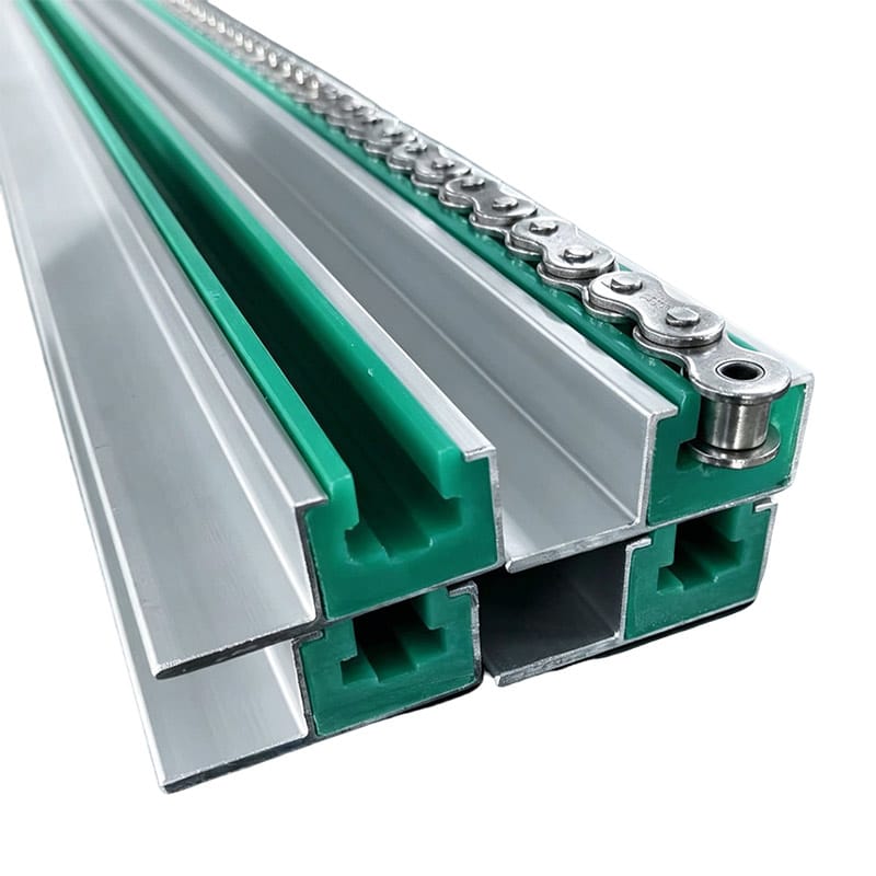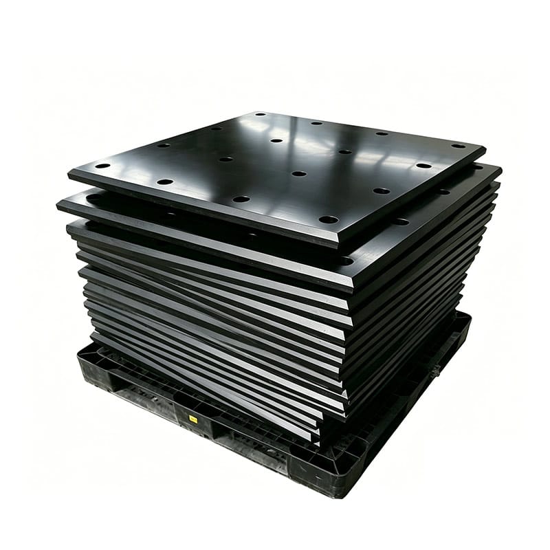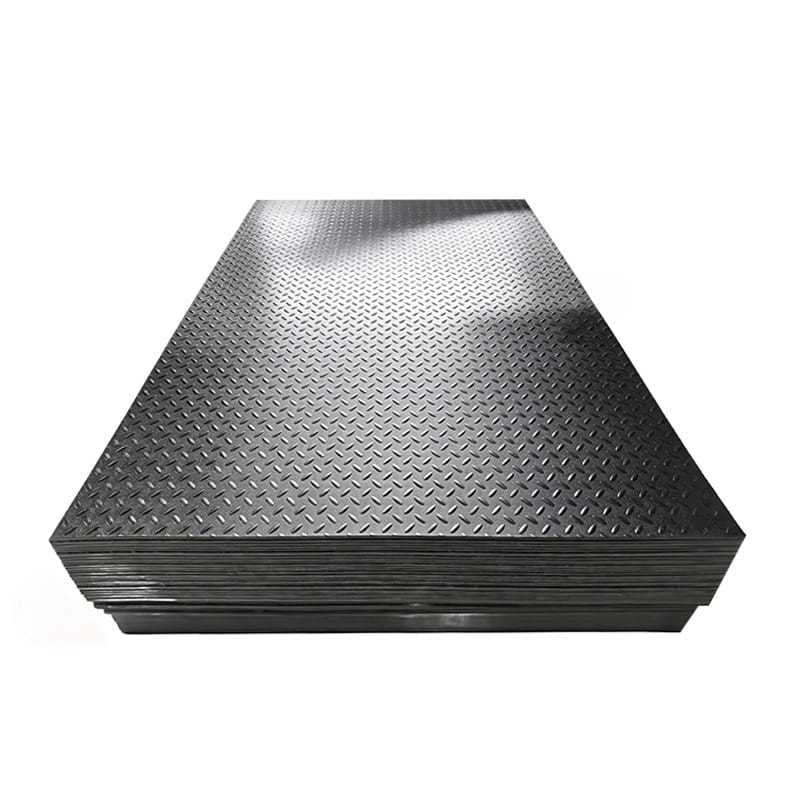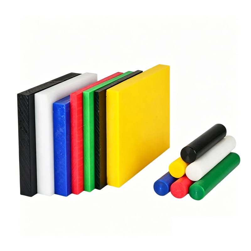
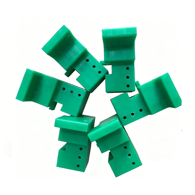
A custom UHMWPE component arrives from the machine shop. The dimensions are checked against the drawing, the inspection report looks acceptable, and the part fits during a trial assembly.
Then the equipment starts running.
Several hours later, the component begins to drag. A sliding block becomes tight on its rail. A guide loses its intended clearance. A wear component that moved freely during installation starts rubbing against its mating surface.
It is easy to assume that the part was machined incorrectly.
Sometimes it was. But in many cases, the more useful investigation begins with UHMWPE part dimensional change under actual operating conditions.
A machined plastic component does not necessarily remain at exactly the same dimensions it had during inspection. Temperature, sustained load, assembly restraint, mating-part movement, machining stress, and the clearance designed into the assembly can all influence what happens after the machine enters service.
This is particularly important when a drawing originally designed for metal is reused for UHMWPE without reconsidering the behavior of the material.
For engineers, OEM buyers and maintenance teams, troubleshooting UHMWPE part dimensional change requires separating three questions:
- Was the part manufactured to the agreed drawing?
- Did its dimensions or shape change during operation?
- Did the surrounding machine geometry change relative to the plastic part?
This guide explains how to diagnose those possibilities before automatically ordering another component with tighter tolerances.
Why UHMWPE Part Dimensional Change Happens
UHMWPE is widely used for industrial wear and sliding components because it offers a useful combination of low friction, toughness, wear resistance and low moisture absorption.
But it is still a thermoplastic.
Its dimensional behavior differs significantly from steel and many other metals.
An installed component may respond to:
- Temperature
- Continuous mechanical load
- Clamping
- Unsupported spans
- Thermal restraint
- Machining
- Time in service
That means a dimension measured at the inspection table may not describe the exact geometry of the component after several hours of operation.
Understanding this difference is central to diagnosing UHMWPE part dimensional change.
Start by Confirming Whether the Part Was Actually In Tolerance
Before investigating temperature or creep, verify the basic manufacturing condition.
Do not assume the part was correct simply because it passed a visual check.
Likewise, do not assume the machine shop made an error simply because the component later binds.
Review:
- Approved drawing revision
- Material specification
- Inspection report
- Measurement method
- Inspection temperature
- Critical dimensions
- Datum references
For custom UHMWPE machined parts, the most important inspection dimensions should correspond to the features that control actual assembly and movement.
Measure the Part Again After Removal
If possible, remove the problematic component and measure it after it has returned to a stable condition.
Compare:
original inspection → in-service condition → post-service inspection
This comparison can provide valuable evidence.
If the part returns close to its original dimensions after cooling and unloading, temperature or operating load may be contributing to the problem.
If the dimensional difference remains, investigate:
- Permanent deformation
- Wear
- Creep
- Assembly damage
- Material removal
- Measurement differences
A single measurement rarely explains the entire UHMWPE part dimensional change problem.
Thermal Expansion Is One of the First Things to Check
Temperature is a common reason why a UHMWPE component that fits during installation becomes tighter during operation.
UHMWPE expands as temperature rises.
Steel components around it also expand, but not necessarily by the same amount.
The relative movement between the two materials can reduce the clearance originally available in the assembly.
Why Long Components Are More Sensitive
Thermal dimensional change increases with component length.
For a simplified engineering estimate:
ΔL = α × L × ΔT
Where:
- ΔL = change in length
- α = coefficient of linear thermal expansion
- L = original length
- ΔT = temperature change
The appropriate coefficient should come from technical data for the actual material grade and relevant conditions.
Do not insert a generic value into a final design without checking the supplier’s data.
The important concept is that a long UHMWPE guide can experience much more absolute movement than a small washer exposed to the same temperature change.
Machine Temperature May Be Higher Than Room Temperature
A component may be inspected at approximately room temperature but operate in a warmer machine.
Heat can come from:
- Friction
- Motors
- Bearings
- Nearby process equipment
- Heated products
- Enclosures
- Ambient factory conditions
If UHMWPE part dimensional change is suspected, measure the actual temperature at the component rather than using the general room temperature.
Useful measurements include:
- Temperature before startup
- Temperature after one hour
- Temperature during steady operation
- Maximum temperature during the shift
This can reveal whether binding appears at approximately the same time the component reaches a higher operating temperature.
Friction Can Create Localized Heating
The process can sometimes become self-reinforcing.
A component starts with slightly too little clearance.
Sliding creates friction.
Friction creates heat.
The UHMWPE expands.
Clearance decreases further.
Friction then increases again.
The operator may only notice the final stage, when movement becomes difficult.
This is why a UHMWPE part dimensional change investigation should look at both temperature and the original running clearance.
Replacing the part with another one at the same dimensions may reproduce the problem.
Clearance Should Be Designed for Operating Conditions
A sliding plastic component needs enough functional clearance for the conditions it will actually experience.
That may include allowance for:
- Manufacturing tolerance
- Thermal expansion
- Mating-part tolerance
- Alignment
- Contamination
- Wear debris
A common mistake is to design the assembly so that it feels precise at room temperature but leaves almost no room for dimensional movement.
For UHMWPE sliding components, the best clearance is not necessarily the smallest clearance.
It is the clearance that allows the assembly to function across its expected operating range.
Why Metal-to-Plastic Conversions Need Special Attention
Many custom UHMWPE parts begin as replacements for components originally made from:
- Steel
- Aluminum
- Bronze
- Another engineering plastic
Copying the outside geometry can be useful as a starting point.
But copying every tolerance and clearance may not be appropriate.
The new material may behave differently in:
- Thermal expansion
- Stiffness
- Creep
- Friction
- Moisture response
If a metal component previously operated with a very small running clearance, using the same clearance for UHMWPE may create problems.
The drawing should be reviewed around the new material rather than treated as material-independent.
Sustained Load Can Cause Creep
Temperature is not the only source of UHMWPE part dimensional change.
Thermoplastics can deform gradually when subjected to sustained stress.
This time-dependent deformation is commonly called creep.
Imagine a UHMWPE block carrying a continuous compressive load.
Even if the initial load does not cause immediate failure, the geometry may gradually change over time.
This can matter in:
- Support blocks
- Loaded guides
- Wear pads
- Spacers
- Sliding bearings
- Clamped components
Creep Is Different from Immediate Elastic Deformation

A material can deform immediately when load is applied and then recover when the load is removed.
Creep refers to deformation that develops with time under sustained load.
The extent depends on factors including:
- Stress
- Temperature
- Time
- Material grade
- Component geometry
Higher temperatures can make time-dependent deformation more significant.
Therefore, a component that works during a short installation test may behave differently after days or months under continuous loading.
Over-Tightened Fasteners Can Distort UHMWPE Parts
Another common cause of apparent UHMWPE part dimensional change is assembly restraint.
Plastic parts should not always be clamped as aggressively as metal components.
Excessive bolt tightening can cause:
- Local compression
- Surface indentation
- Distortion
- Bowing
- Changed clearance
The part may have been perfectly within tolerance before installation.
After fastening, its geometry may no longer match the inspection condition.
Look Around Mounting Holes
If binding occurs after assembly, inspect for:
- Deep washer impressions
- Distortion around bolts
- Cracks
- Pulled material
- Bowed surfaces
Compare dimensions before and after tightening if possible.
The problem may be installation-induced rather than a machining error.
Rigid Mounting Can Restrict Thermal Movement
Long UHMWPE components should not automatically be rigidly locked at every mounting point.
If a long guide is fixed so that thermal movement cannot occur, expansion may appear as:
- Bowing
- Buckling
- Local bulging
- Increased contact pressure
Depending on the application, the mounting concept may use a controlled fixed point combined with features that allow movement elsewhere.
The exact arrangement should be designed for the component and equipment.
This is particularly relevant for long conveyor guides and wear strips.
The Mating Part May Be the Component That Changed
When a UHMWPE part binds, attention naturally focuses on the plastic component.
But the mating structure should also be inspected.
Possible problems include:
- Steel rail misalignment
- Shaft movement
- Frame distortion
- Bearing wear
- Loose brackets
- Thermal movement
- Installation error
Suppose a sliding UHMWPE block fits a steel rail correctly during inspection.
If the rail becomes misaligned after the machine warms up, the block can bind even if its own dimensions remain acceptable.
A complete UHMWPE part dimensional change investigation should therefore measure the assembly, not just the plastic part.
Alignment Can Mimic Dimensional Growth
A small alignment error can produce symptoms similar to an oversized component.
For example, two parallel rails may be correctly spaced at one end but converge slightly along their length.
A UHMWPE slider can move freely through the first section and bind farther along the machine.
The immediate conclusion might be:
“The plastic expanded.”
But the actual problem may be rail geometry.
Before changing the UHMWPE dimensions, measure:
- Parallelism
- Straightness
- Rail spacing
- Shaft alignment
- Mounting position
This avoids solving the wrong problem.
Contamination Can Reduce Running Clearance
Dust and debris can also create apparent UHMWPE part dimensional change.
Particles can accumulate between sliding surfaces.
Common contaminants include:
- Sand
- Dust
- Metal chips
- Product debris
- Packaging fragments
- Dried process material
Even a small buildup can matter in an assembly designed with limited clearance.
Hard particles can also increase friction and create additional heat.
When troubleshooting, inspect both the UHMWPE surface and mating component for embedded debris or scoring.
UHMWPE Has Low Moisture Absorption, but Do Not Ignore the Entire Assembly
UHMWPE is often chosen partly because its moisture absorption is low compared with some other engineering plastics.
That can be advantageous in:
- Washdown environments
- Outdoor equipment
- Food processing
- Wet conveyors
However, low moisture absorption does not mean every dimensional problem in a wet machine can be ignored.
Water can affect:
- Contamination
- Lubrication
- Temperature
- Metal corrosion
- Adjacent materials
If another plastic in the assembly absorbs more moisture, relative dimensions can also change.
The complete assembly should be evaluated.
Machining Stress and Part Geometry Can Influence Final Shape
Material removal changes the balance of a component.
This is especially relevant for:
- Long thin parts
- Asymmetric profiles
- Deep pockets
- Large flat panels
After machining, a part may relax slightly.
A manufacturer experienced with OEM/ODM custom UHMWPE components may use machining sequences and fixturing strategies intended to manage this behavior.
However, geometry still matters.
A very thin asymmetric design can be more sensitive than a compact, well-supported part.
Clamping During Machining Can Affect Inspection Results
UHMWPE is softer than metal.
If excessive clamping pressure is used during machining, the part may deform in the fixture.
The machine cuts the distorted shape.
When the clamps are released, the part relaxes.
This can create dimensional differences.
A similar problem can occur during measurement if the part is forced flat against a fixture rather than inspected in its free state.
For critical components, buyer and supplier should agree on:
- Inspection orientation
- Support method
- Temperature
- Datum setup
This makes dimensional results more repeatable.
Why Tighter Tolerances May Make the Problem Worse
When a part binds, a common response is:
“Make the next batch more precise.”
That is not always the correct solution.
If the real issue is insufficient operating clearance, making the part more consistently close to the nominal dimension does not fix the design.
The correct response may instead involve:
- Changing nominal dimensions
- Increasing functional clearance
- Adding thermal movement
- Revising mounting
- Correcting alignment
Tolerance and clearance are not the same thing.
A ±0.05 mm tolerance does not tell you whether the assembly has enough clearance to operate at its maximum temperature.
Separate Manufacturing Tolerance from Functional Clearance
This distinction is essential.
Manufacturing tolerance defines how much a finished dimension may vary from the drawing.
Functional clearance defines the space available between mating components.
A successful design needs both.
For example, if two mating parts each have manufacturing variation, the worst-case combination must still provide enough functional clearance under operating conditions.
This is why tolerance stack-up should be considered before blaming UHMWPE part dimensional change alone.
Measure the Problem at Operating Temperature When Possible
If binding occurs only after the machine runs, room-temperature inspection may not capture the condition.
Where safe and technically practical, collect:
- Part temperature
- Mating-part temperature
- Clearance before startup
- Clearance after warm-up
- Time until binding
This information is much more useful than simply reporting:
“The part becomes too large.”
A repeatable relationship between temperature and binding strongly helps narrow the cause.
Check Whether the Problem Is Reversible
One of the most useful troubleshooting questions is:
Does the part work normally again after the equipment cools?
If yes, thermal effects become a stronger candidate.
If no, investigate:
- Creep
- Permanent deformation
- Wear debris
- Fastener distortion
- Machine alignment
- Surface damage
The difference between reversible and permanent UHMWPE part dimensional change can guide the next inspection step.
A Practical Troubleshooting Process
Rather than immediately modifying the drawing, use a structured process.
Confirm the Drawing Revision
Make sure the supplied component was manufactured from the correct file.
Review the Original Inspection Report
Check whether the critical dimensions were actually measured.
Measure the Part at Room Temperature
Record the free-state dimensions before installation.
Measure the Mating Components
Confirm that rails, shafts, slots and frames are within their intended geometry.
Record Initial Clearance
Do not rely on “it feels loose enough.”
Measure the available space where practical.
Run the Equipment
Record:
- Time
- Load
- Speed
- Temperature
Document When Binding Begins
Identify whether the problem corresponds with:
- Temperature increase
- Increased load
- Longer operating time
- Contamination
Inspect After Shutdown
Check whether the part returns to normal after cooling and unloading.
This sequence provides much stronger evidence than repeatedly changing part dimensions by trial and error.
What Information Should You Send the UHMWPE Part Manufacturer?
If a custom part binds in service, provide the supplier with enough information to investigate the application.
Drawing Information
Send:
- 2D drawing
- STEP file
- Revision number
- Critical dimensions
Inspection Information
Provide:
- Original measured dimensions
- Inspection temperature if known
- Measurement method
- Dimensional report
Operating Conditions
Provide:
- Minimum temperature
- Normal temperature
- Maximum temperature
- Load
- Speed
- Operating hours
Assembly Information
Provide:
- Mating-part dimensions
- Original clearance
- Fastener arrangement
- Support spacing
- Photos
Failure Information
Provide:
- Time until binding
- Location of contact
- Surface marks
- Temperature when the problem appears
- Whether the problem disappears after cooling
These details allow a manufacturer to investigate UHMWPE part dimensional change instead of guessing from a photograph.
Design Changes That May Solve Repeated Binding
Once the cause has been identified, possible design changes may include:
Increasing Functional Clearance
Useful when operating-temperature movement was not adequately considered.
Changing Mounting Slots
Useful where a long component needs controlled thermal movement.
Revising the Fixed Point
Long parts may need a defined reference point while allowing expansion elsewhere.
Increasing Section Stiffness
Useful when deformation rather than thermal growth is the main problem.
Reducing Sustained Stress
Useful when creep contributes to dimensional change.
Correcting Mating-Part Alignment
Necessary when the plastic component is not actually the source of the interference.
The correct solution depends on evidence from the actual assembly.
Common UHMWPE Dimensional Troubleshooting Mistakes
Assuming the Machining Supplier Is Automatically at Fault
A binding problem does not automatically prove that the part was machined incorrectly.
First verify:
- Drawing revision
- Material specification
- Original inspection results
- Assembly condition
- Operating temperature
- Mating-part geometry
If the part met the agreed drawing during inspection, the root cause may lie elsewhere in the system.
Tightening the Tolerance Without Changing Clearance
A tighter manufacturing tolerance does not automatically solve an interference problem.
If the nominal dimensions leave insufficient running clearance at operating temperature, producing the part more accurately can still reproduce the same failure.
Before tightening tolerances, determine whether the assembly actually needs:
- More nominal clearance
- A different mounting method
- Thermal expansion allowance
- Better alignment
Tolerance control and functional clearance should be treated separately.
Ignoring Operating Temperature
A part inspected at room temperature may behave differently after hours of operation.
If binding appears only after warm-up, temperature should be measured and included in the investigation.
Ignoring operating temperature can lead to repeated replacement of correctly machined parts.
Ignoring Creep
A short installation check does not reproduce months of continuous loading.
If the part supports sustained force, time-dependent deformation may contribute to the problem.
Review:
- Continuous load
- Contact pressure
- Temperature
- Time in service
before assuming the geometry will remain unchanged indefinitely.
Measuring Only the Plastic Part
The surrounding equipment can also move.
Inspect:
- Rails
- Shafts
- Frames
- Bearings
- Mounting brackets
- Adjacent components
A UHMWPE component can bind because its mating parts are no longer aligned, even when the plastic itself remains close to its original dimensions.
Copying Metal Clearances
A clearance that worked for a steel or bronze component may not be suitable for UHMWPE.
Different materials respond differently to:
- Temperature
- Load
- Time
- Restraint
When converting a metal component to UHMWPE, the assembly should be reviewed rather than copied dimension for dimension.
Ignoring Fastener Torque
Over-tightening can locally compress or distort UHMWPE.
This may alter the shape of an otherwise correctly manufactured part.
Check for:
- Washer impressions
- Bowing
- Local crushing
- Distortion around mounting holes
Fastener design should match the material and component geometry.
Replacing the Part Without Recording the Failure
Once the old part is discarded, useful evidence is lost.
Before replacement, record:
- Wear marks
- Contact zones
- Temperature
- Remaining clearances
- Distortion
- Installation orientation
These records can help prevent the same problem from returning.
UHMWPE Part Dimensional Change FAQ
Does UHMWPE Expand When Heated?
Yes. UHMWPE experiences thermal expansion, so dimensions can change as temperature changes.
The amount of movement depends on:
- Material grade
- Part length
- Temperature difference
- Installation restraint
Long parts generally show more absolute dimensional change than short parts exposed to the same temperature increase.
Why Does My UHMWPE Part Fit Cold but Bind After Running?
Common causes include:
- Thermal expansion
- Frictional heating
- Insufficient running clearance
- Mating-part movement
- Misalignment
- Excessive clamping
If the part becomes free again after cooling, temperature-related effects should be investigated first.
Does UHMWPE Absorb Water and Swell?
UHMWPE has very low moisture absorption compared with many other engineering plastics.
For most industrial applications, water absorption is not usually the main cause of large dimensional change.
However, the complete assembly should still be considered because:
- Other materials may absorb moisture
- Water can change lubrication
- Corrosion can alter mating surfaces
- Contamination can reduce clearance
Can UHMWPE Creep Under Load?
Yes. Like other thermoplastics, UHMWPE can deform gradually under sustained stress.
The degree of creep depends on:
- Stress level
- Temperature
- Duration
- Part geometry
- Material grade
This is especially important for continuously loaded support blocks, guides and spacers.
Should I Use Tighter Tolerances to Prevent Binding?
Not necessarily.
Binding is often caused by insufficient functional clearance rather than loose machining tolerance.
A better approach is to review:
- Nominal dimensions
- Worst-case tolerance stack-up
- Operating temperature
- Mating-part dimensions
- Required running clearance
Can a UHMWPE Part Be Correct at Inspection but Wrong in Service?
Yes.
A part may meet the drawing at inspection and still become unsuitable in operation because of:
- Temperature
- Creep
- Assembly distortion
- Machine movement
- Incorrect functional clearance
This is why inspection and application conditions should be evaluated together.
How Should Long UHMWPE Parts Be Mounted?
Long components should be mounted in a way that considers thermal movement.
Depending on the design, this may involve:
- A defined fixed point
- Slotted holes
- Floating locations
- Expansion gaps
The correct method depends on part length, temperature range and machine geometry.
Can Over-Tightened Bolts Make a UHMWPE Part Bind?
Yes.
Excessive clamping can compress or deform plastic around the fasteners and change the component’s functional geometry.
Mounting hardware should be designed and installed with the plastic material in mind.
What Information Should I Send if a Custom UHMWPE Part Is Binding?
Useful information includes:
- 2D drawing
- STEP file
- Drawing revision
- Original inspection report
- Operating temperature
- Load
- Speed
- Mating-part dimensions
- Installation photos
- Wear or contact marks
- Time until binding occurs
This allows the manufacturer to investigate the application rather than simply remaking the same part.
Conclusion
A custom UHMWPE component that fits during inspection but binds in service is not necessarily a machining defect.
The problem may be caused by UHMWPE part dimensional change, but that dimensional change can come from several different sources.
The most common factors include:
- Thermal expansion
- Frictional heating
- Creep under sustained load
- Excessive fastener pressure
- Restricted thermal movement
- Insufficient functional clearance
- Mating-part misalignment
- Contamination
- Machine-frame movement
The most effective troubleshooting process is therefore based on evidence.
Compare the part before operation, during the problem condition, and after removal. Measure the mating equipment. Record temperature, load and operating time. Determine whether the interference is reversible or permanent.
Most importantly, do not respond to every binding problem by automatically tightening tolerances.
A more precise part can still fail if the original design does not provide enough room for thermal movement, assembly variation and real operating conditions.
Paowo Group manufactures custom UHMWPE machined parts for industrial wear, sliding, guide and equipment applications, with support for drawings, samples and OEM production requirements.
For repeat OEM projects, Paowo Group also provides OEM/ODM customization covering drawing review, material selection, machining, inspection and repeat-order control.
Request a Quote
If a custom UHMWPE component fits correctly during inspection but begins to bind after installation, send Paowo Group your:
- 2D drawing
- STEP file
- Original inspection data
- Operating temperature
- Load and speed
- Mating-part dimensions
- Installation photos
- Contact or wear marks
- Time until the problem appears
These inputs can help distinguish between a machining issue, thermal movement, creep, assembly distortion and equipment alignment before the next batch is produced.