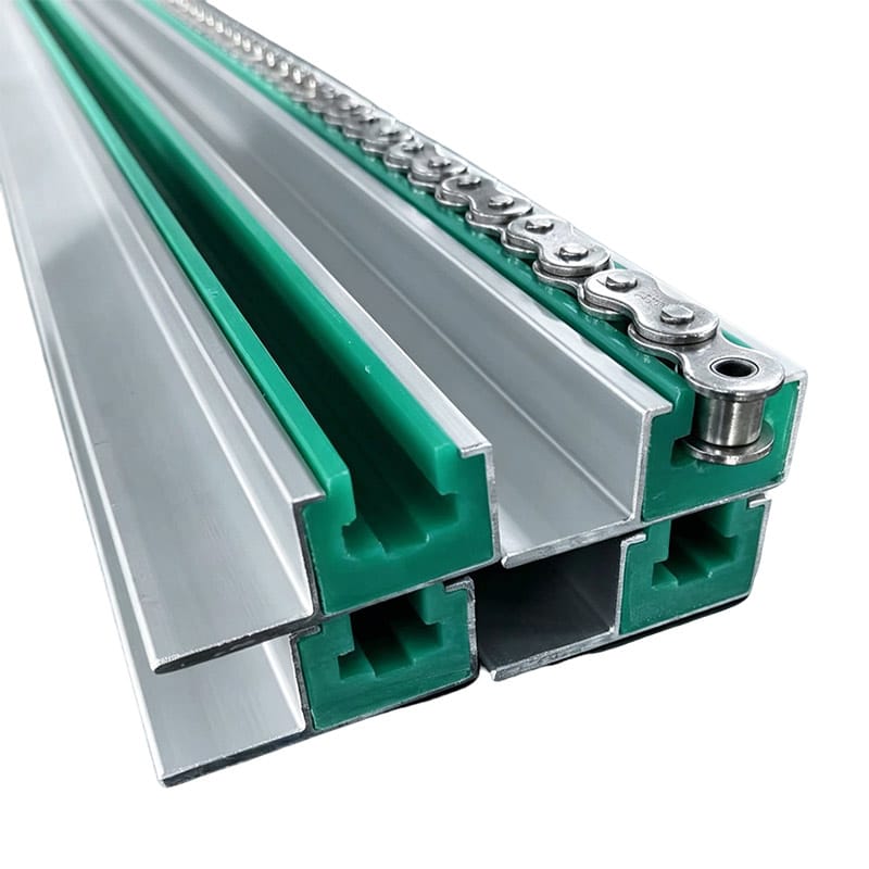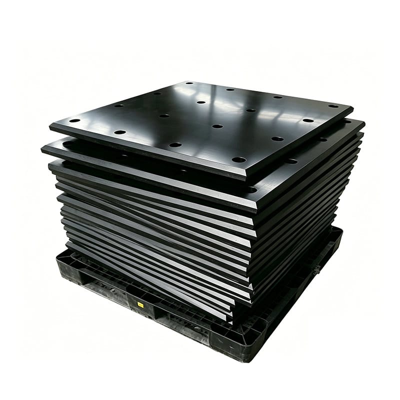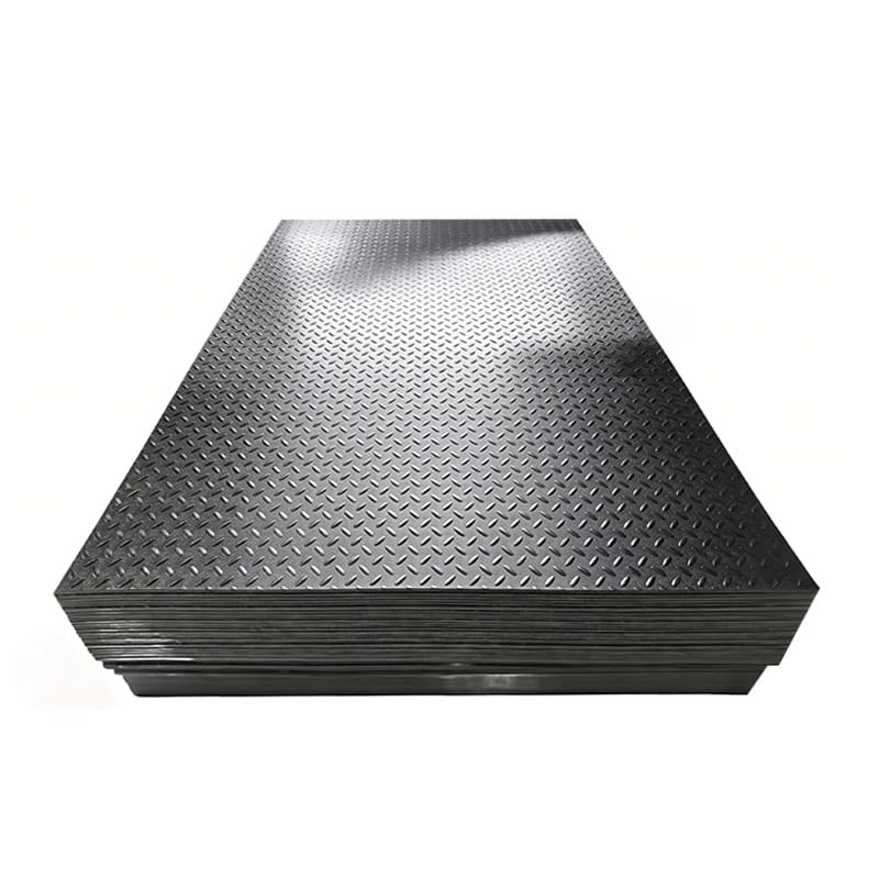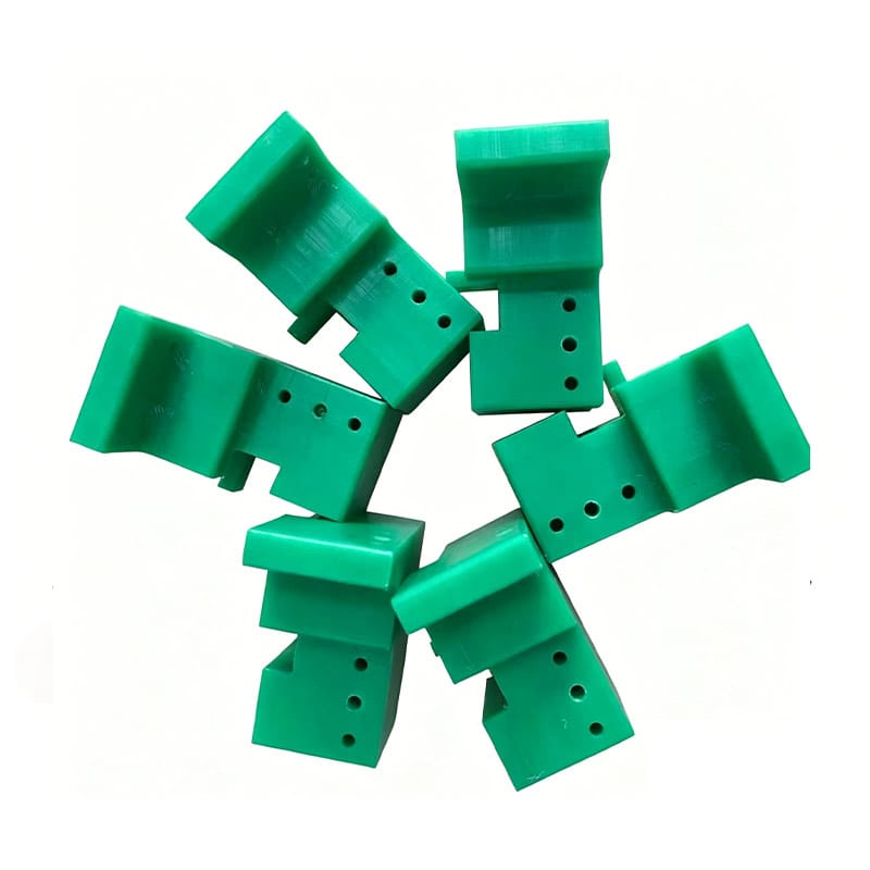
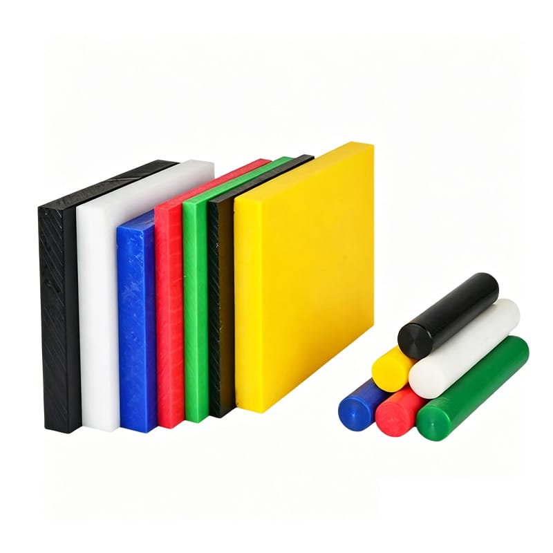
A UHMWPE plate can look flat before machining, remain flat while clamped to a CNC table, and then develop a noticeable bow shortly after the finished component is released.
For buyers, this can be confusing.
The immediate assumption is often that the CNC machine was inaccurate or that the raw material was defective. Those possibilities should be checked, but UHMWPE sheet warping can also result from the interaction between material condition, part geometry, machining sequence, clamping, temperature and the amount of material removed from each side.
UHMWPE is not steel.
It is a thermoplastic with different stiffness, thermal behavior and response to mechanical restraint. A machining strategy that works well for a rigid metal plate may not produce the same dimensional behavior in a large plastic component.
This becomes especially important for:
- Long guide rails
- Large wear plates
- Thin machined panels
- Wide flat components
- Parts with deep pockets on one side
- Components requiring tight flatness
The objective should therefore not be to promise that every machined sheet will remain perfectly flat under every condition. A more useful approach is to understand why UHMWPE sheet warping occurs and design the part, process and inspection method to reduce the risk.
Paowo Group supplies UHMWPE engineering plastic sheets and manufactures custom UHMWPE machined parts for industrial applications where dimensional requirements need to be considered together with actual material behavior.
What Does UHMWPE Sheet Warping Look Like?
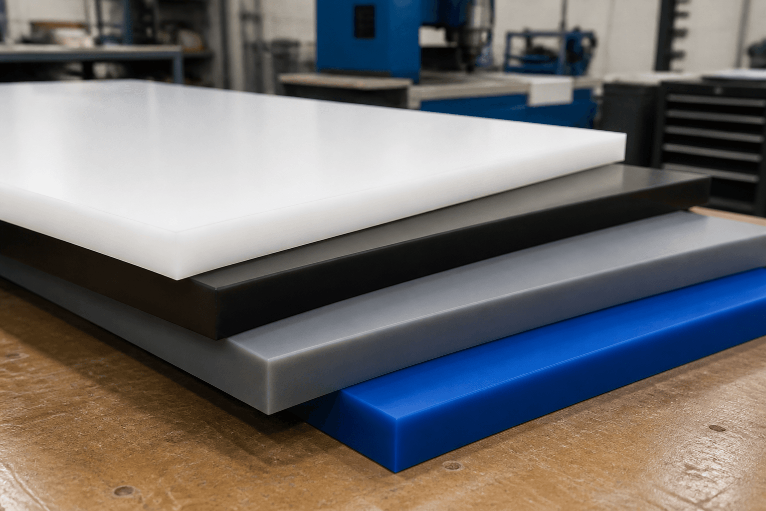
UHMWPE sheet warping does not always appear in the same form.
A finished component may show:
- Bowing along its length
- Curvature across its width
- Twisting from corner to corner
- Raised edges
- A center section that no longer sits flat
- Local distortion near machined pockets
The deformation may appear:
- Immediately after unclamping
- Several minutes later
- After the component cools
- During storage
- After installation
- After the machine reaches operating temperature
The timing provides useful troubleshooting information.
If the part changes shape immediately after the clamps are removed, fixturing or material-removal balance may be involved.
If UHMWPE sheet warping appears after thermal exposure, operating temperature and restraint deserve closer attention.
Why UHMWPE Does Not Behave Like a Metal Plate
UHMWPE combines useful wear and sliding characteristics with relatively low stiffness compared with metals.
That matters during machining.
A steel plate can often tolerate:
- High clamping force
- Aggressive one-sided machining
- Small unsupported spans
without showing the same level of deformation as a comparable plastic part.
UHMWPE requires a different mindset.
The manufacturer should consider:
- How the blank is supported
- Where clamps are positioned
- How much material is removed
- Whether both sides are machined
- How heat is controlled
- How the part is supported after machining
Understanding these differences is the first step toward controlling UHMWPE sheet warping.
Residual Stress Can Contribute to UHMWPE Sheet Warping
Raw polymer stock can contain internal stresses from manufacturing and cooling.
The exact level depends on the particular:
- Material
- Sheet dimensions
- Manufacturing process
- Cooling history
A sheet may appear flat because those internal stresses are balanced.
Machining changes that balance.
If a significant amount of material is removed from one side, stresses that were previously balanced across the section may redistribute.
The result can be UHMWPE sheet warping after machining.
This does not mean every warped part proves the sheet had unacceptable residual stress.
Part geometry and machining strategy can create similar symptoms.
The entire process should be reviewed.
Why Uneven Material Removal Is a Major Risk
Imagine starting with a thick UHMWPE plate.
The finished component requires one side to remain largely unchanged while the other side receives:
- Several deep pockets
- Grooves
- Recesses
- Large surface machining
The final cross-section is no longer balanced.
This type of asymmetric machining can increase the risk of UHMWPE sheet warping because the material has been removed unevenly.
Large Pockets Are Particularly Important
A large pocket can leave:
- Thin floor sections
- Flexible walls
- Uneven remaining thickness
Even if every machined dimension is correct while the part is clamped, the component may relax once released.
For large CNC-machined UHMWPE components, the design should therefore be reviewed before manufacturing rather than assuming machining alone can control final flatness.
Consider Removing Material from Both Sides
Where the design allows, a balanced machining strategy may help reduce UHMWPE sheet warping.
Instead of removing all machining allowance from one face, the manufacturer may consider machining both sides in stages.
For example:
- Rough one side.
- Release or reposition the component.
- Rough the opposite side.
- Allow the part to stabilize where appropriate.
- Finish critical surfaces.
The exact process depends on:
- Part geometry
- Raw material
- Final tolerance
- Equipment
There is no universal sequence for every UHMWPE component, but the general principle is useful:
avoid unnecessary imbalance in stock removal.
Clamping Pressure Can Temporarily Hide Warping
One of the most important causes of confusion in UHMWPE sheet warping investigations is fixture pressure.
Suppose a slightly bowed UHMWPE blank is pulled flat against a CNC table using strong clamps.
While the part is clamped, the machine cuts it as though the blank were perfectly flat.
The inspection performed in the same restrained state may appear acceptable.
Then the clamps are removed.
The material returns toward its unrestrained shape.
The buyer may see a warped finished component even though the machining program itself followed the intended coordinates.
Excessive Clamping Can Distort UHMWPE
Because UHMWPE is more compliant than steel, excessive clamping can locally compress or bend the blank.
Potential consequences include:
- Thickness variation after release
- Bowing
- Distorted holes
- Changed pocket depths
- UHMWPE sheet warping
The objective is to hold the component securely without forcing it into an artificial geometry.
This is where experience machining engineering plastics matters.
Support the Part, Not Just the Edges
Large sheets may need support across their area.
If a wide plate is supported only around the perimeter, the center can move during machining.
Appropriate fixture design may involve:
- Support blocks
- Sacrificial plates
- Vacuum fixtures
- Distributed clamping
The suitable method depends on geometry.
For thin components, good support can be especially important in controlling UHMWPE sheet warping and maintaining dimensional consistency.
Machining Heat Can Affect Dimensional Stability
Cutting creates heat.
UHMWPE is a thermoplastic, so temperature should be considered during machining and inspection.
Heat can result from:
- Dull tools
- Excessive rubbing
- Poor chip evacuation
- Inappropriate cutting parameters
- Long continuous tool engagement
If the component becomes significantly warmer during machining, its dimensions can temporarily change.
If it is then measured immediately, the result may not represent its later stabilized dimensions.
Controlling heat is therefore part of reducing UHMWPE sheet warping risk.
Sharp Tools Help Reduce Heat
Sharp cutting tools allow the machine to cut the polymer rather than rub against it excessively.
This can improve:
- Chip formation
- Surface quality
- Temperature control
- Edge finish
A dull tool can generate unnecessary heat and leave rougher surfaces.
Tool condition should therefore be monitored throughout a production batch.
This is especially relevant where UHMWPE sheet warping or tight finished dimensions are concerns.
Chip Evacuation Matters Too
UHMWPE can generate long or continuous chips during machining.
If these chips remain around the cutting zone, they can interfere with:
- Tool movement
- Heat removal
- Surface finish
Effective chip evacuation helps maintain a more controlled machining environment.
A clean machining process does not eliminate all dimensional movement, but it removes one avoidable source of temperature-related variation.
Why Part Thickness Matters
Thin parts are generally more flexible than thick parts of the same plan dimensions.
That makes them more sensitive to:
- Clamping
- Uneven stock removal
- Handling
- Storage
A 20 mm plate and a 5 mm finished panel should not be expected to behave identically just because both are UHMWPE.
As remaining thickness decreases, the risk of visible UHMWPE sheet warping can increase, particularly for large panels.
Designers should therefore consider:
- Length-to-thickness relationship
- Width-to-thickness relationship
- Unsupported area
- Pocket depth
rather than specifying flatness independently from geometry.
Long UHMWPE Components Require Special Attention
Long parts amplify dimensional effects.
Examples include:
- Conveyor wear strips
- Guide rails
- Machine slide plates
- Long structural wear components
Even modest curvature can become visually obvious over a long distance.
Long parts are also more affected by:
- Storage orientation
- Thermal expansion
- Support spacing
For long machined parts, UHMWPE sheet warping should be discussed before quotation if flatness or straightness is functionally critical.
Why Tight Flatness Requirements Can Increase Cost
Flatness is not just another drawing number.
A very tight flatness requirement on a large UHMWPE component can influence:
- Raw stock selection
- Machining strategy
- Fixturing
- Inspection
- Scrap risk
Before applying metal-like flatness tolerances, ask:
Does the machine actually need that level of flatness?
If the component will be bolted onto a rigid flat steel surface, the functional requirement may differ from a free-standing precision plate.
Avoiding unnecessarily restrictive requirements can reduce both cost and UHMWPE sheet warping disputes.
Define Whether Flatness Is Measured Free or Restrained
This is an important drawing and inspection detail.
Should the part be inspected:
- Resting freely?
- Supported at specified points?
- Bolted to the machine?
- Clamped to a reference fixture?
Those are different conditions.
If the drawing simply states a flatness value without specifying the functional inspection condition, buyer and supplier may interpret the requirement differently.
For applications sensitive to UHMWPE sheet warping, agree on inspection support before production.
Temperature During Inspection Should Be Controlled
A large UHMWPE component measured immediately after machining may still be warmer than the inspection environment.
Allowing the component to reach a stable inspection condition can improve measurement repeatability.
For demanding projects, buyer and supplier should agree on:
- Measurement environment
- Stabilization period where appropriate
- Support condition
- Measurement method
This helps distinguish real UHMWPE sheet warping from temporary dimensional movement associated with temperature.
Storage Can Cause or Increase Apparent Warping
Manufacturing is not the final stage affecting the part.
Storage matters too.
Imagine a long thin UHMWPE panel leaning diagonally against a wall for weeks.
Gravity and the material’s flexibility can influence shape over time.
Poor storage can therefore contribute to UHMWPE sheet warping after machining.
Store Large Flat Parts Appropriately
Where practical, large sheets and panels should be supported in a way that avoids unnecessary sustained bending.
Important storage considerations include:
- Flat support
- Uniform stacking
- Avoiding heavy point loads
- Temperature
- Long-term orientation
Long narrow guides may require distributed support along their length.
The best arrangement depends on the finished part geometry.
Packaging Can Affect Long Parts During Shipping
A carefully machined guide can still arrive bowed if it is packaged without enough support.
For long components, packaging should prevent:
- Excessive bending
- Unsupported overhang
- Heavy parts loading onto thin parts
This means packaging requirements should be included when UHMWPE sheet warping is a critical concern.
A dimensional inspection report from the factory cannot control damage or deformation caused by poor transportation support.
Operating Temperature Can Change the Installed Shape
Some components remain flat after machining but change during machine operation.
This is a different problem from immediate post-machining deformation.
UHMWPE responds to temperature changes.
If a long part is mounted rigidly and then heated, its attempt to expand may create:
- Bowing
- Buckling
- Increased contact pressure
In this situation, what appears to be UHMWPE sheet warping may actually be an installation and thermal-expansion issue.
Long Parts May Need Movement Allowance
Depending on the design, mounting arrangements may use:
- A defined fixed point
- Slotted mounting holes
- Floating positions
- Expansion gaps
The purpose is to control the part’s position while allowing appropriate dimensional movement.
The correct arrangement depends on:
- Part length
- Operating temperature range
- Equipment geometry
Do not add slots automatically without engineering review, but do not assume a long plastic component should be locked like a steel plate either.
Installation on an Uneven Surface Can Distort the Part
A flat UHMWPE component installed onto a warped or uneven steel frame may conform partly to that surface.
Once fasteners are tightened, the finished assembly can appear distorted.
Before blaming UHMWPE sheet warping, inspect the substrate.
Check for:
- Bent steel
- Weld distortion
- Corrosion buildup
- Uneven mounting pads
- Debris underneath the part
The mounting surface may be creating the final shape.
Fastener Torque Can Create Local Distortion
Excessively tightened bolts can compress UHMWPE locally.
If fasteners are distributed unevenly, the resulting distortion can appear as:
- Waviness
- Raised sections
- Bowing around holes
The appropriate fastening system should consider:
- Washer size
- Hole geometry
- Material thickness
- Required movement
For large panels, uniform installation practices can help reduce assembly-induced UHMWPE sheet warping.
Why Deep Countersinks Need Careful Design
Countersunk holes are common in wear liners and sliding plates because they keep fastener heads below the working surface.
However, a deep countersink removes material around the hole.
On thin components, this can reduce local stiffness.
If many deep countersinks are concentrated near one edge, they can contribute to a more flexible geometry.
Countersink design should therefore be considered together with:
- Finished thickness
- Hole spacing
- Edge distance
rather than treated as a purely cosmetic feature.
Raw Sheet Flatness Should Be Checked Before Machining
If finished flatness matters, inspect the raw material before machining.
Documenting starting condition helps answer an important troubleshooting question:
Was the blank already bowed before machining?
The manufacturer can record:
- Raw thickness
- Raw flatness
- Material identification
- Sheet dimensions
This provides a stronger basis for diagnosing later UHMWPE sheet warping.
Material Batch Information Can Help Troubleshooting
If multiple parts from one batch show unusual behavior while earlier parts did not, material batch information can be useful.
Record where available:
- Material grade
- Batch
- Supplier
- Sheet size
This does not automatically prove the raw material is responsible, but it helps separate material variables from machining and design variables.
For repeat OEM programs, traceability can make UHMWPE sheet warping investigations much more systematic.
How to Reduce UHMWPE Sheet Warping During Design
The best time to address dimensional stability is before machining begins.
Design strategies may include:
Avoid Unnecessarily Thin Large Panels
If stiffness matters, retaining more section thickness may help.
Avoid Extreme One-Sided Pockets
Where possible, keep geometry reasonably balanced.
Identify Only Truly Critical Flatness Requirements
Do not apply precision-metal expectations where the application does not need them.
Allow Appropriate Thermal Movement
Long installed parts should be reviewed for temperature effects.
Consider Mounting Support
A component fully supported by a machine structure has different requirements from a free-standing panel.
These decisions can have more influence on UHMWPE sheet warping than simply requesting tighter machining tolerance.
How to Reduce UHMWPE Sheet Warping During Machining
The manufacturing plan may include several controls.
Inspect the Raw Blank
Confirm obvious bowing or distortion before machining.
Use Appropriate Fixturing
Support the part without unnecessarily forcing it flat.
Control Clamping Force
Avoid distorting the plastic simply to hold it securely.
Balance Material Removal
Where possible, avoid extreme one-sided stock removal.
Use Sharp Tools
Reduce rubbing and excess heat.
Manage Chip Evacuation
Keep the cutting zone clear.
Allow Stabilization Before Final Inspection
Where dimensional requirements justify it, inspect the component under an agreed stable condition.
Not every component requires every step, but these measures provide a useful framework for controlling UHMWPE sheet warping.
How to Reduce Warping During Shipping and Storage
After machining:
- Support long components adequately
- Avoid prolonged unsupported bending
- Keep different parts organized
- Avoid heavy point loads on thin panels
- Use packaging appropriate to the geometry
If the part has strict flatness requirements, include packaging expectations in the purchase specification.
This helps keep manufacturing controls from being undone during transportation.
How to Troubleshoot a Warped UHMWPE Part
When UHMWPE sheet warping has already occurred, use a structured investigation.
Confirm the Drawing Revision
Make sure the correct geometry was manufactured.
Record the Warped Shape
Document whether the part is:
- Bowed
- Twisted
- Wavy
- Locally distorted
Measure the Raw and Finished Thickness
Uneven finished thickness may provide clues.
Review the Machining Sequence
Determine how much material was removed from each side.
Review Fixturing
Ask whether the part was forced flat during machining.
If a naturally bowed blank was clamped tightly against the machine table, the finished component may appear flat while restrained but move after release.
Review:
- Clamp locations
- Clamp pressure
- Support points
- Vacuum fixture use
- Whether the part was measured while still clamped
Check Temperature
Determine whether deformation appeared:
- During machining
- Immediately after machining
- After cooling
- During machine operation
If the part was inspected while still warm, the measured geometry may not represent its stabilized condition.
Temperature-related dimensional movement should therefore be separated from permanent UHMWPE sheet warping.
Review Storage and Shipping
Confirm how the part was supported after machining.
Check whether it was:
- Stored flat
- Leaned vertically
- Unsupported across a long span
- Loaded under other parts
- Poorly supported during transport
Long or thin UHMWPE parts can change shape if they remain under sustained bending.
Inspect the Machine Mounting Surface
The problem may be created during installation rather than during machining.
Check the steel or supporting structure for:
- Unevenness
- Weld distortion
- Corrosion buildup
- Debris
- Bent brackets
- Misaligned mounting points
A flat plastic part can become distorted when it is tightened onto an uneven surface.
Review Fastener Installation
Check whether bolts or clamps were tightened unevenly.
Look for:
- Local compression
- Washer impressions
- Distortion around holes
- Raised areas between fasteners
If the installed shape differs substantially from the free-state shape, the mounting method may be contributing to the problem.
Compare Free-State and Installed Measurements
Where practical, measure the component both:
- Removed from the machine
- Installed in the machine
This helps determine whether UHMWPE sheet warping originates in the part itself or is being imposed by the assembly.
A structured review prevents every dimensional problem from being blamed on raw material or CNC accuracy without evidence.
Common UHMWPE Sheet Warping Mistakes
Tightening Flatness Tolerance Without Changing the Design
If the component is very thin, long or heavily pocketed, simply specifying tighter flatness may not address the reason it is moving.
The geometry itself may need revision.
Machining One Side Heavily and Expecting No Movement
Removing a large amount of material from only one face can increase the risk of dimensional movement.
Where practical, machining strategy should consider the balance of material removal.
Forcing the Blank Flat During Machining
This can create a misleading result.
A part may appear perfect on the CNC table and then bow once the fixture is released.
Measuring the Part While It Is Still Warm
Machining heat can temporarily change dimensions.
If flatness or thickness is critical, measurement conditions should be agreed in advance.
Storing Long Parts Unsupported
A long guide or plate leaning unsupported for an extended period may develop visible bowing.
Storage should match the part geometry.
Ignoring the Mounting Surface
An uneven machine frame can distort a correctly machined UHMWPE component.
Always inspect both the part and the structure onto which it is installed.
Assuming Every Warped Part Means Bad Raw Material
Material condition is one possible cause, but so are:
- Machining sequence
- Fixturing
- Heat
- Geometry
- Packaging
- Installation
The root cause should be established before rejecting an entire material batch.
Using Metal-Style Design Rules Without Review
UHMWPE has different stiffness and thermal behavior from steel or aluminum.
A geometry originally designed for metal may need changes in:
- Thickness
- Support
- Tolerance
- Mounting
Ignoring Operating Temperature
A part that remains flat at room temperature may change shape after the equipment heats up.
Long UHMWPE components should be reviewed for thermal movement during service.
UHMWPE Sheet Warping FAQ
Why Does UHMWPE Warp After CNC Machining?
Common contributors include:
- Residual stress
- Uneven material removal
- Excessive clamping
- Machining heat
- Thin geometry
- Poor support after machining
The actual cause may involve more than one factor.
Can UHMWPE Sheet Warping Be Completely Eliminated?
It is not realistic to guarantee zero dimensional movement for every UHMWPE part and operating condition.
However, the risk can often be reduced significantly through:
- Better part design
- Controlled raw material
- Appropriate fixturing
- Balanced machining
- Temperature control
- Correct storage
Does Machining Both Sides Help Reduce Warping?
It can help in some applications because it may create a more balanced material-removal process.
The appropriate sequence depends on:
- Part thickness
- Geometry
- Amount of stock removed
- Final tolerance
It should be planned for the specific component.
Why Is My UHMWPE Part Flat While Clamped but Bent After Release?
The fixture may be forcing the part into a flat condition.
When the clamps are removed, the material can move back toward its natural unrestrained shape.
This is why free-state inspection is important when flatness matters.
Can Heat Cause UHMWPE Sheet Warping?
Yes.
Heat generated during machining or operation can contribute to dimensional movement.
Potential sources include:
- Dull tools
- Excessive rubbing
- High-friction operation
- Nearby process heat
Actual temperature should be measured when thermal effects are suspected.
Are Thicker UHMWPE Parts Less Likely to Warp?
Greater thickness generally increases section stiffness.
However, thickness alone does not eliminate UHMWPE sheet warping caused by:
- Residual stress
- Severe one-sided machining
- Clamping
- Temperature
- Poor installation
Should UHMWPE Sheets Be Stored Flat?
Large flat sheets and machined panels should generally be supported in a way that avoids unnecessary sustained bending.
Long guide rails may need support along their length.
The exact storage arrangement depends on the part geometry.
Can a Warped UHMWPE Part Be Straightened?
Possibly, depending on:
- Degree of deformation
- Geometry
- Cause
- Final tolerance
- Application
However, correcting one warped part without identifying the root cause may allow the same problem to return in the next batch.
Should I Specify Very Tight Flatness for UHMWPE?
Only if the application genuinely requires it.
Very tight flatness requirements on large or thin UHMWPE components can increase:
- Manufacturing complexity
- Inspection effort
- Cost
- Scrap risk
The requirement should be based on function.
Can Poor Packaging Cause UHMWPE Sheet Warping?
Yes.
A long or thin component can deform if it is transported with:
- Insufficient support
- Heavy point loads
- Excessive bending
Packaging should be considered part of dimensional control for sensitive parts.
Can Over-Tightened Bolts Warp a UHMWPE Part?
Yes.
UHMWPE can deform locally under excessive clamping pressure.
Uneven bolt tightening can also force a large plate into a non-flat installed condition.
UHMWPE Warping Troubleshooting Checklist
When requesting technical support, provide the following information.
Material
- UHMWPE grade
- Raw sheet thickness
- Raw sheet dimensions
- Material batch if available
- Manufacturing route if known
Finished Part
- Length
- Width
- Finished thickness
- Pocket depth
- Groove depth
- Drawing revision
- Required flatness
Warping Condition
- Maximum measured bow
- Direction of bow
- Twist if present
- Location of deformation
- Photographs
- When the warping first appeared
Machining Information
- Amount removed from each side
- Roughing and finishing sequence
- Clamping method
- Support method
- Whether the part was inspected while restrained
- Tooling information if relevant
Temperature
- Approximate machining temperature
- Inspection temperature
- Operating temperature
- Whether distortion changes after cooling
Storage and Shipping
- Storage orientation
- Duration of storage
- Packaging method
- Shipping support
Installation
- Mounting surface condition
- Fastener arrangement
- Support spacing
- Bolt or clamp locations
- Installed photographs
These inputs provide a much stronger basis for reviewing UHMWPE sheet warping than a message saying only that the finished plate is “bent.”
Conclusion
UHMWPE sheet warping after machining is usually best understood as a dimensional-stability issue involving the entire manufacturing and installation process.
Possible contributors include:
- Residual material stress
- Uneven stock removal
- Excessive clamping
- Machining heat
- Thin or asymmetric geometry
- Inspection condition
- Storage
- Transportation
- Thermal expansion
- Installation restraint
The correct solution is therefore not always tighter machining tolerance.
In many cases, better results come from reviewing the component before production.
That may include:
- Balancing material removal
- Supporting the blank correctly
- Reducing unnecessary clamp pressure
- Controlling heat
- Defining realistic flatness requirements
- Improving packaging
- Allowing appropriate thermal movement
- Checking the mounting surface
For buyers, the most useful drawings are those that distinguish functional requirements from cosmetic precision.
If only one surface must mate accurately to a machine frame, that should be clear. If free-state flatness is critical, the inspection condition should be defined.
This allows the manufacturer to design the machining and inspection process around how the component will actually be used.
Paowo Group supplies UHMWPE engineering plastic sheets and manufactures custom UHMWPE machined parts for industrial wear, guide, sliding and OEM applications.
Request a Quote
If you are troubleshooting UHMWPE sheet warping or planning a large CNC-machined UHMWPE component, send Paowo Group your:
- 2D drawing
- STEP file
- UHMWPE grade
- Raw and finished thickness
- Overall dimensions
- Flatness requirement
- Pocket and groove details
- Operating temperature
- Mounting method
- Existing warping measurements
- Photos of the component
These inputs can help identify whether the main risk comes from material condition, machining sequence, fixturing, geometry, storage or installation before the next production batch is released.